Compute Engines and Data Flow within Tensix
The matrix and vector engines (FPU and SFPU) are integral to Tensix’s compute capabilities. They are designed to efficiently handle a wide range of mathematical operations, particularly those common in machine learning. However, they are highly specialized and do not operate like traditional CPU-attached vector and matrix units. Instead of having direct access to CPU registers and memory, these engines use their own registers and rely on the unpacker and packer to move data between SRAM and the compute engines.
Understanding the data flow between the register sets, the unpacker and packer, and the engines is critical for achieving optimal performance and resource utilization. Please refer to the relevant hardware and ISA documentation for more details.
Component introduction
A critical design aspect to understand is that all registers have a fixed element count. Each vector register holds exactly N elements, where N depends on the kernel configuration and the specific register set. This differs from x86 SSE/AVX or ARM NEON and is more similar to some GPU warp/wavefront designs. The size of the registers may also change between hardware generations. Thus, a program that depends on a specific register dimension must be rewritten to work across generations. Compute APIs provided by the Metalium kernel library, like matmul_tiles and sin_tiles, abstract away these details, allowing you to focus on the algorithm rather than the underlying hardware specifics.
For example, the SFPU LReg (the SFPU’s internal vector register) on Wormhole is 32 elements wide, with each element being 32 bits. A conventional SIMD register design would imply a capacity of 1024 bits per register, which could hold 128 elements of int8 data. However, the SFPU treats the register as holding 32 elements of at most 32 bits each, regardless of the actual data type.
Several key components work together to perform computations within Tensix:
Unpacker: Reads data from L1 memory and converts it into the format required by the compute engines, placing it into the
SrcA,SrcB, orDstregisters.Packer: Takes results from the compute engines (from the
Dstregisters), formats them, and moves them back into L1.Vector engine (SFPU): Executes complex vector operations, handling data in parallel for efficient computation.
Matrix engine (FPU): Specializes in large-scale matrix operations, optimized for high throughput.
The compute engines rely on four main register sets:
SrcA: The first source register of the matrix engine.
SrcB: The second source register of the matrix engine.
Dst: The destination register set for the matrix engine, also used by the vector engine. This register set is exposed in the higher-level API.
LReg: Internal registers within the SFPU for holding vector data during computation.
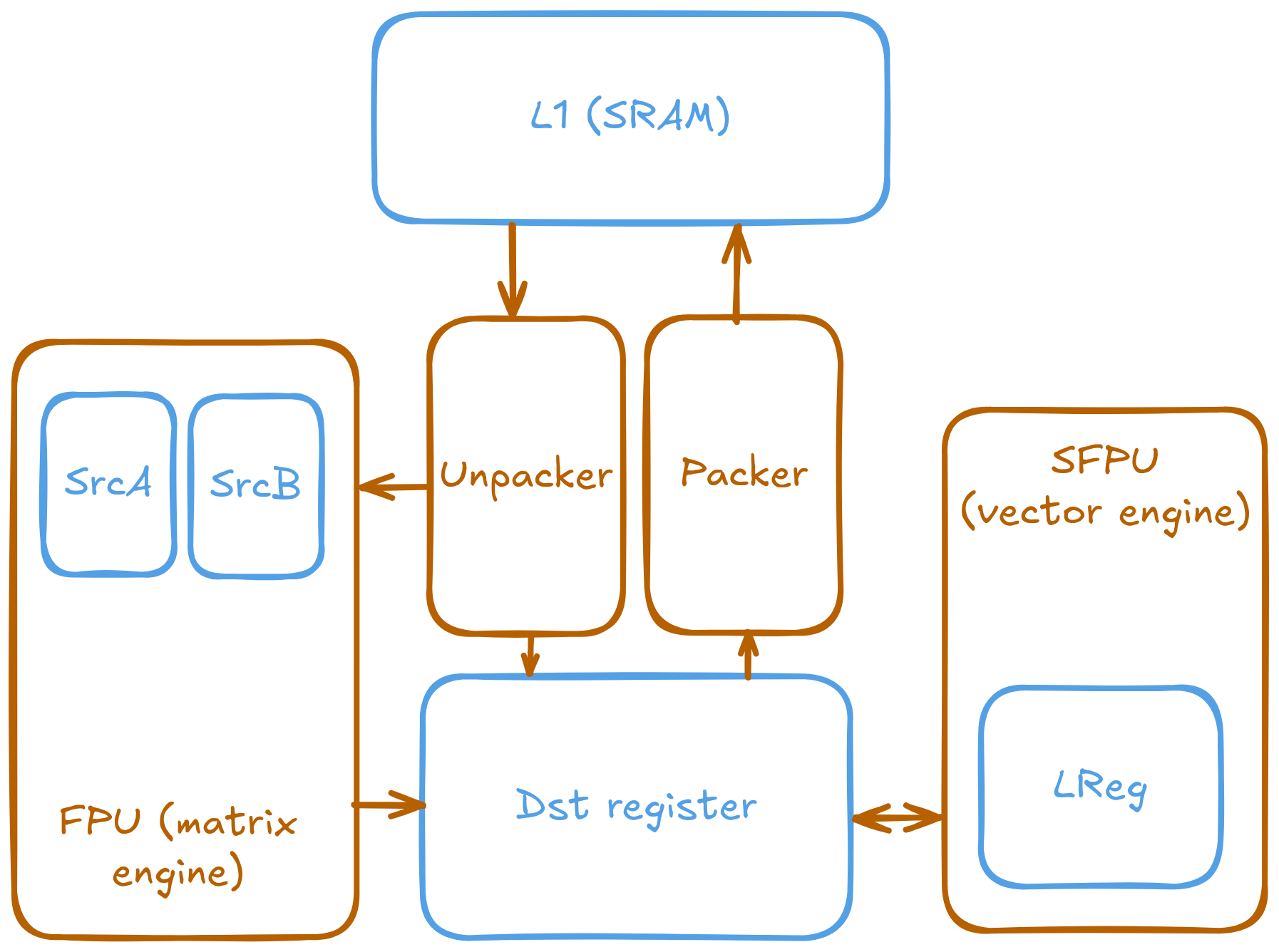
The following image illustrates the connection between the different components and the registers they can access.
Note
The register names are historical and may not clearly reflect their roles. The matrix engine (FPU) was developed before the vector engine (SFPU), and the names SrcA, SrcB, and Dst were chosen based on their use in matrix operations: SrcA and SrcB as source operands, and Dst as the destination. These names remained unchanged when the vector engine was added.
SrcA and SrcB are physical registers inside the matrix engine. The names might suggest references to memory locations, but they are just hardware registers used for computation. And unlike Dst, SrcA and SrcB are single registers, not a register set.
Note
Although a compute kernel is written as a single piece of code, it is compiled into three separate binaries, each running on a different RISC-V core (T0-2) within the Tensix. Synchronization is required to ensure correct data flow and avoid race conditions between these components.
Furthermore, the unpacker, packer, SFPU, and FPU are not processing cores and cannot make control flow decisions on their own. The RISC-V cores issue commands to the compute engines and manage data flow between them. Explicit synchronization may be needed to ensure the engines have finished their work before the RISC-V cores proceed.
The connection between the unpacker, packer, SFPU, FPU, and the various registers is crucial for efficient data processing within the Tensix architecture.
The data format within the compute registers can differ from the format used for storage in SRAM. The unpacker and packer are responsible for converting between these formats in hardware. This allows compute kernels to work with standard data types, like floating-point or integers, while data in SRAM can remain in a more compact representation, such as a block floating-point format.
This hardware-accelerated type conversion is more efficient than performing it in software. For example, instead of using the compute engines to decompress quantized data, the unpacker can perform this conversion directly. This design makes compute kernels independent of the storage data format and reduces execution time and power consumption.
The separation of data movement (unpacker/packer) and computation (FPU/SFPU) requires an initialization step. Before invoking a compute operation, the unpacker and packer must be configured to handle the correct input and output data formats. This is critical for ensuring correct results and enabling hardware performance optimizations.
Dst register
The Dst register set is the primary workspace for compute kernels and the only register set directly exposed through the compute APIs. It serves as the destination for the matrix engine and as both a source and destination for the vector engine.
The unpacker and packer handle data movement between L1 memory and the Dst registers. The kernel library provides functions for these operations:
// copy_tile: Unpacks a tile from a circular buffer into a Dst register.
// Before calling, ensure the source circular buffer has data (e.g., using cb_wait_front).
copy_tile(CBIndex::c_0, /*tile_offset_in_cb*/0, /*dst_idx*/0);

// pack_tile: Packs a tile from a Dst register into a circular buffer.
// Before calling, ensure the destination circular buffer has space (e.g., using cb_reserve_back).
pack_tile(/*dst_idx*/0, CBIndex::c_16, /*tile_offset_in_cb*/0);
Since the unpacker, packer, and compute engines operate concurrently on different RISC-V cores, access to the Dst registers must be synchronized. The kernel library provides a set of functions to manage this, ensuring that different hardware components do not access the registers simultaneously.
A typical compute loop follows this synchronization pattern:
// 0. Wait for input data to be available in the input circular buffers.
// e.g. cb_wait_front(...)

// 1. Acquire Dst registers for the unpacker and math core.
//    This must happen after waiting for input data.
tile_regs_acquire();

// Unpack data and perform math operations.
// e.g., copy_tile(...), matmul_tiles(...), add_tiles(...)

// 2. Commit the results, transferring ownership of Dst registers to the packer.
tile_regs_commit();

// At this point, the kernel can pop from input CBs and reserve space in output CBs.
// This overlaps communication with the packer's work.
// e.g. cb_pop_front(...), cb_reserve_back(...)

// 3. Wait for the packer to be ready to access the Dst registers.
tile_regs_wait();

// Pack results from Dst registers to output circular buffers.
// e.g., pack_tile(...)

// 4. Release the Dst registers, making them available for the next iteration's acquire step.
tile_regs_release();

// Announce that data has been written to the output CBs.
// e.g., cb_push_back(...)
Note
The ordering of circular buffer operations (cb_wait_front, cb_pop_front, cb_reserve_back, cb_push_back) is flexible but constrained by data dependencies. The pattern shown in the example minimizes stalls by overlapping communication with the packer’s work. Unpacking into Dst registers requires first acquiring them, and packing can only begin after waiting for the packer to be ready. However, by no means it is the only correct ordering.
The acquire_dst and release_dst functions are deprecated. The tile_regs_* family of functions provides more explicit control and should be used instead.
Warning
Even if a kernel does not pack any data, tile_regs_commit and tile_regs_release must still be called in sequence after computation to correctly manage the register state. Failure to do so results in undefined behavior.
The capacity and behavior of the Dst register set are configured on the host through the ComputeKernelConfig struct when creating a kernel. Two key parameters control its operation. Assuming using the standard 32x32 tiles:
-
fp32_dest_acc_en: Configures the data width of theDstregisters.false(default):Dstholds 16 tiles of 16-bit data.true:Dstholds 8 tiles of 32-bit data.
-
dst_full_sync_en: Controls a double-buffering mechanism for theDstregisters.false(default): Enables double-buffering. Only half of theDstregisters are available to the kernel at a time. This allows the packer to work on one half while the math core and unpacker work on the other, overlapping computation and packing to improve performance.true: Disables double-buffering. The entireDstregister set is available to the kernel. This serializes computation and packing, which may be simpler but can reduce throughput.
The number of available tiles is determined by the combination of these two settings:
|
|
|
|---|---|---|
|
8 |
16 |
|
4 |
8 |
// Example host-side kernel configuration
auto kernel_id = tt::tt_metal::CreateKernel(
    program,
    "path/to/your/compute/kernel.cpp",
    core,
    tt::tt_metal::ComputeConfig{
        .fp32_dest_acc_en = true, // Use 32-bit Dst registers
        .dst_full_sync_en = false  // Enable double-buffering
    }
);

// Number of Dst registers can be checked using ttnn::get_dest_reg_count(const ComputeKernelConfig&)
Warning
Setting fp32_dest_acc_en = true only allocates 32-bit per-element storage space in the Dst registers; it does not guarantee that computations are performed in 32-bit precision. For example, the matrix engine might still compute in bfloat16 and store the result in a 32-bit container. Also, the matrix engine’s maximum accuracy is TF32 (19 active bits), which is less than the full 32-bit precision. On the other hand, the vector engine does support the full 32-bit precision (with some limitations as it does not strictly follow IEEE 754 rounding).
Accessing Dst register tiles beyond the number available for the current configuration results in undefined behavior.
Matrix engine/FPU
The matrix engine, or FPU, performs the bulk of computation for most AI and machine learning workloads. FPU operations take data from SrcA and SrcB (if needed) and write or accumulate results into Dst. The FPU also supports common matrix operations such as element-wise multiplication, addition, subtraction, and pooling.
FPU operations require initialization before execution. This setup configures the unpacker, packer, and FPU for the specific operation (e.g., matrix multiplication). Re-initialization is not required for repeated operations with the same source, destination, and data type parameters.
The FPU uses dedicated registers for each operand, and the unpacker can directly write to these registers. The API requires specifying the circular buffer and tile index for each operand. Because the FPU writes results to the Dst registers, the output tile index must also be specified. FPU compute functions often takes the following parameters, depending on the number of operands:
Index of the circular buffer for the first operand, and the offset of the tile from the buffer’s read head.
(If applicable) Index of the circular buffer for the second operand, and the offset of the tile from the buffer’s read head.
Offset, in number of tiles, within the
Dstregisters to write the result.
For example, to perform matrix multiplication:
// Configure (un)packer and FPU for matmul mode.
// The unpacker is configured based on cb_in0 and cb_in1.
// The packer is configured based on cb_out.
mm_init(CBIndex::c_0, CBIndex::c_1, CBIndex::c_16);

// Repeated computation can be performed without re-initialization.
for(int i=0; i < 8; i++) {
    // Wait for data to be available in the input circular buffers.
    cb_wait_front(CBIndex::c_0, 1); cb_wait_front(CBIndex::c_1, 1);

    // Acquire Dst registers for the math core.
    tile_regs_acquire();

    // Perform matrix multiplication:
    // - Take tile 0 from CB 0 and tile 0 from CB 1.
    // - Place the result into Dst tile 0.
    //              cb_in0     cb_in1        in0_offset  in1_offset  dst_idx
    matmul_tiles(CBIndex::c_0, CBIndex::c_1, 0         , 0         , 0);

    // Commit the results, transferring ownership of Dst registers to the packer.
    tile_regs_commit();

    // Pop tiles from input CBs and reserve space in the output CB.
    cb_pop_front(CBIndex::c_0, 1); cb_pop_front(CBIndex::c_1, 1);
    cb_reserve_back(CBIndex::c_16, 1);

    // Wait for the packer to be ready.
    tile_regs_wait();

    // Pack the result from Dst tile 0 into the output CB.
    pack_tile(/*src_dst_idx*/0, CBIndex::c_16, /*tile_offset_in_cb*/0);

    // Announce that data has been written to the output CB.
    cb_push_back(CBIndex::c_16, 1);

    // Release Dst registers for the next iteration.
    tile_regs_release();
}
Warning
The same input circular buffers (e.g., cb_in0 and cb_in1) must be specified in both mm_init and matmul_tiles. Using different circular buffers between these calls results in undefined behavior, as the unpacker may interpret the data incorrectly or read from invalid memory.
The configuration information for the unpacker and packer is derived from the circular buffer metadata. In the example above, circular buffers 0 and 1 are used to configure the unpacker to place their data into SrcA and SrcB, respectively. The packer is configured to pack data into the format expected by circular buffer 16.
Vector engine/SFPU
The vector engine, or SFPU, is designed for high-throughput processing of vector data. Unlike matrix engine APIs, SFPU APIs require the user to explicitly unpack data into the Dst registers before performing computations and then pack the results back into L1 memory. This design enables easier chaining of operations.
The vector engine APIs also require an initialization phase. The init_sfpu function configures the unpacker and packer to handle the data types of the input and output circular buffers. Unlike the matrix engine, the unpacker cannot be configured for a second operand; it assumes that all input circular buffers contain the same underlying data type. As with the matrix engine, ensure that parameters are consistent between initialization and computation calls to avoid undefined behavior.
For example, to compute the element-wise sum of two tiles:
// Configure the (un)packer based on the data formats of the CBs.
init_sfpu(tt::CBIndex::c_0, tt::CBIndex::c_16);

for(int i=0; i < 8; i++) {
    cb_wait_front(CBIndex::c_0, 1); cb_wait_front(CBIndex::c_1, 1);
    tile_regs_acquire();

    // Unpack the first tile from CB 0 into Dst tile 0.
    copy_tile(CBIndex::c_0, /*tile_offset_in_cb*/0, /*dst_idx*/0);
    // Unpack the first tile from CB 1 into Dst tile 1.
    copy_tile(CBIndex::c_1, /*tile_offset_in_cb*/0, /*dst_idx*/1);

    // Add Dst tiles 0 and 1 together. Store the result back into Dst tile 0.
    // Pseudocode: dst_tile[0] = dst_tile[0] + dst_tile[1]
    add_binary_tile(/*dst_idx_a*/0, /*dst_idx_b*/1, /*dst_idx_out*/0);
    // More operations can be chained here, e.g., applying sigmoid.
    // sigmoid_tile(0);

    tile_regs_commit();
    cb_pop_front(CBIndex::c_0, 1); cb_pop_front(CBIndex::c_1, 1);
    cb_reserve_back(CBIndex::c_16, 1);
    tile_regs_wait();
    pack_tile(/*dst_idx*/0, CBIndex::c_16, /*tile_offset_in_cb*/0);
    cb_push_back(CBIndex::c_16, 1);
    tile_regs_release();
}
Note
copy_tile_init can be used to re-configure the unpacker to consume different data formats from circular buffers. If CBIndex::c_0 and CBIndex::c_1 contain different data types, the unpacking part of the above example can be rewritten as follows:
copy_tile_init(CBIndex::c_0);
copy_tile(CBIndex::c_0, /*tile_offset_in_cb*/0, /*dst_offset_tiles*/0);
copy_tile_init(CBIndex::c_1);
copy_tile(CBIndex::c_1, /*tile_offset_in_cb*/0, /*dst_offset_tiles*/1);
Note that copy_tile_init is always needed when unpacking FP32 values into 32-bit Dst registers. init_sfpu assumes a 16-bit storage size and sets up the unpacker for bfloat16, which would cause a loss of precision if an explicit initialization is not performed.
Similarly, the pack_reconfig_data_format function and its variants can be used to change the packer’s output data format. This is necessary when a computation produces multiple tiles that must be written to circular buffers with different data formats. For example, to pack two tiles into two separate circular buffers, each with a unique data format:
pack_reconfig_data_format(CBIndex::c_16);
pack_tile(/*src_idx*/0, CBIndex::c_16, /*tile_offset_in_cb*/0);
pack_reconfig_data_format(CBIndex::c_17);
pack_tile(/*src_idx*/1, CBIndex::c_17, /*tile_offset_in_cb*/0);
After data is unpacked into the Dst registers, the vector engine can load data from Dst into its internal LReg registers directly, without involving other hardware blocks. For more details on programming the SFPU, see the Low Level Kernels programming guide. The dst_reg variable provides an LReg-sized view into the Dst registers. For example, on Wormhole and Blackhole, LReg is 32 elements wide, so the first Dst tile corresponds to dst_reg[0:31]. To illustrate:
void sfpu_example_function() {
    // Load the first 32 elements of the 1st tile into an LReg.
    vFloat vec1 = dst_reg[0];
    // Load the first 32 elements of the 2nd tile into another LReg.
    vFloat vec2 = dst_reg[32];

    // Store the results back into the Dst registers.
    dst_reg[0] = vec1;
    dst_reg[32] = vec2;
}
Due to the internal structure of tiles, dst_reg[0:3] typically contains the first face of the tile, dst_reg[4:7] contains the second face, and so on.