Overview
SEP combines a VeeR CPU, boot ROM, system peripherals, lifecycle controls, and cryptographic accelerators. The chapters below describe these functions in reading order; the block diagram shows their hardware connections.
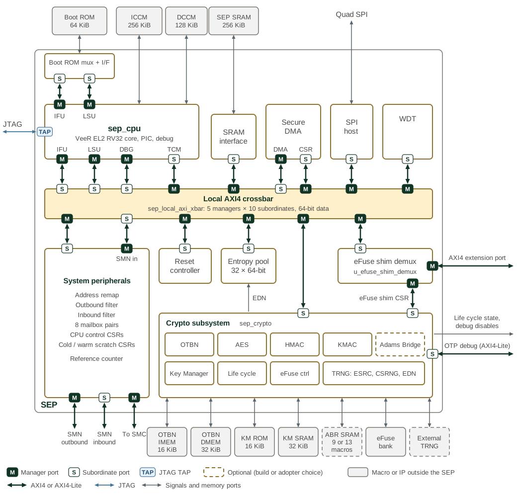
Every AXI4 link carries a manager port (M) at the initiating end and a subordinate port (S) at the other. The local crossbar has five managers: the CPU IFU, LSU and debug ports, the DMA, and inbound SMN traffic after the system peripherals' inbound filter. Its ten subordinates are the CPU TCM port, the SRAM interface, the DMA registers, the SPI host, the watchdog, the system peripherals, the reset controller, the entropy pool, the crypto subsystem and the eFuse shim demux. SEP AXI4 connectivity gives the permitted paths. The IFU and LSU reach the boot ROM through a dedicated AXI mux rather than the crossbar, and the IFU crossbar port reaches only the SRAM. The eFuse shim demux sends accesses in the eFuse shim CSR window to the crypto subsystem and the rest of the external aperture to the AXI4 extension port.
The grey boxes are the memory macros and IP that the integration layer
instantiates outside the SEP. The Adams Bridge and its SRAMs are present only
when the build defines SEP_ABR_EN; the Adams Bridge uses nine SRAMs, plus
four masked copies when ABR_MASKING_EN is set. The external TRNG is an
adopter choice. Interrupt lines to the CPU PIC are not drawn; see
Interrupts.
1. Responsibilities
SEP is the Root of Trust (RoT) of the chiplet with the highest security privilege. SEP provides a physically isolated execution environment for highly sensitive security services. The following are some examples:
-
Secure boot: The SEP ROM BL0 image uses non-volatile public keys to conduct authentication verification on the loaded BL1 software images.
-
Secure lifecycle control: SEP implements a secure lifecycle controller to manage function, debug and test access to the chiplet according to fuse configuration, in-field demotion, and secret token inputs.
-
Device attestation: SEP offers support to device attestation by recording the boot process and device configuration followed attestation using public key infrastructure.
-
Cryptography service: SEP offers secure key services to the rest of the system together with cryptography acceleration. SEP also implements True Random Number Generator (TRNG) to provide random numbers for SEP itself and the rest of the system.
-
User authentication: Similar to secure boot, user authentication is another authentication service SEP offers. Besides feature control that can be tied to the authentication result, SEP software can also tie the authentication result to the secret key derivation to ensure that bypass of the user authentication leads to a useless system.
The SEP is responsible for ensuring that the chiplet and overall packaged system composed of multiple chiplets remains secure from adversaries. This means that SEP ensures the system
-
Runs correctly with the intended firmware and data protected by digital signatures
-
Guards against malicious data input to SEP, SMC and the debug/test infrastructure
-
Prevents exfiltration of private or secret data on all exits, including side channels
-
Prevents privilege escalation which would enable illegal operations
A consolidated description of OCAH use cases is available in Use Cases.
2. Threat Model
The threat model defines the attacks considered by SEP.
3. Attack Countermeasures
Attack Countermeasures describes the corresponding architectural, debug and test protections.
4. Clocks and Resets
SEP uses one system clock (clk_i) that clocks the CPU, interconnect and all cryptographic
subsystems. Additional clock roots supply reference counter (clk_ref_i), watchdog timer (clk_wdt_i),
entropy sampler (entropy_rosc_sample_clk_i) and CPU debug (jtag_tck_i). Clocks and
Resets describes their distribution and links to software reset sequencing.
5. CPU
The CPU provides a JTAG debug interface, tightly coupled instruction and data memories, and two scratch register banks. The proposed Alarm Aggregation Processor is deferred to a later generation.
6. Boot ROM
The immutable BL0 firmware starts the SEP and authenticates the next boot stage. The Boot ROM chapter owns the hardware layout and boot-flow summary.
7. Interconnect
AXI4 connects the CPU, system peripherals and cryptographic subsystem. External interfaces include inbound and outbound system AXI paths, the peripheral extension and JTAG. UART and GPIO services can be reached through SMC.
8. Interrupts
The interrupt chapter identifies PIC sources and the separate NMI, timer, software-interrupt and memory-error paths.
9. Peripherals
DMA provides data movement and inline hashing. Mailboxes carry host service requests. SPI supplies flash access; the watchdog provides bark and bite events. The peripheral subsystem chapter describes their integration and extension interface.
10. Security and Lifecycle
The OTP fuse controller, token processing, security-disable logic, lifecycle controller and test-mode controls govern access to security assets and debug.
11. Cryptographic Subsystem
AES, HMAC-SHA2, KMAC-SHA3, OTBN and Adams Bridge provide acceleration. Entropy Source, DRBG and entropy distribution supply random material. Key Manager owns the Key and Policy Vault and accelerator key-sideload interfaces.
12. Memory Map
The memory map summarizes CPU and external address views and links to each block’s register reference. Technology-specific ROM, SRAM, OTP and entropy macros sit outside SEP and connect through its dedicated interfaces. These include BL0 ROM, ICCM, DCCM, scratch SRAM, KM ROM/SRAM and OTBN IMEM/DMEM.
See Clocks and Resets.
See SEP clock tree.