I2C Controller
The I2C controller is based on the OpenTitan I2C design. Controller and target behavior, clock stretching, arbitration, timing setup, and programming sequences are specified in the OpenTitan theory of operation and the OpenTitan programmer’s guide.
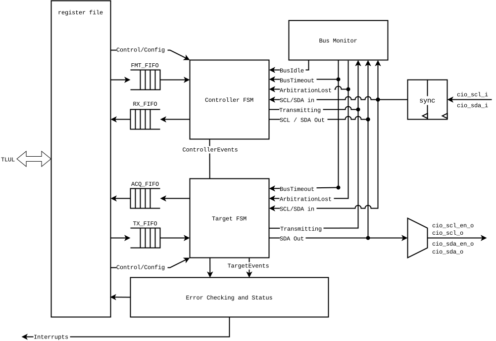
Figure 1 shows the upstream core.
1. OCAH Modifications
-
AXI4-Lite register interface in place of the OpenTitan TileLink host port.
-
Wrapper register blocks
i2c_ctrlandi2c_wraparound the OpenTitan register bank.
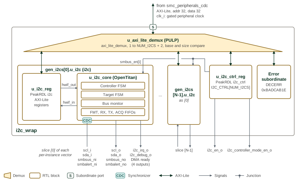
Figure 2 shows the OCAH wrapper around that core. i2c_wrap
has one AXI4-Lite slave port, with 32-bit address and data, and runs on a
single clock, clk_i; in the SMC that is the gated peripheral clock, and the
bus reaches it through smc_peripherals_cdc. Parentheses after an
instance name give its module or, for a block taken from another project,
that project. The demux
u_axi_lite_demux, a PULP axi_lite_demux, compares the address against
the base and size of each register map and selects one of NUM_I2CS + 2
ports: one per instance, the shared control map, and an error slave that
answers DECERR with read data 0xBADCAB1E. The SMC sets NUM_I2CS to 3.
Each instance, gen_i2cs[i].u_i2c, is the OpenTitan core u_i2c_core with
its register bank replaced by u_i2c_reg, an AXI4-Lite register block that
PeakRDL generates from i2c.rdl. The register block drives the core through
hwif_out and takes status back through hwif_in. The core keeps the
OpenTitan controller and target FSMs, bus monitor and FMT, RX, TX and ACQ
FIFOs, sized by the *_FIFO_DEPTH parameters, and synchronizes the SCL,
SDA, SMBus SUS and SMBus ALERT inputs to clk_i with two-flop synchronizers;
the synchronizer badge on the edge of u_i2c_core marks them. The wrapper
adds no synchronizers of its own.
The shared block u_i2c_ctrl_reg, generated from i2c_ctrl.rdl, holds one
I2C_CTRL register per instance. Its SMBUS_EN field drives that instance’s
smbus_en input, which masks smbalert_ni while low. Its I2C_EN and
I2C_CONTROLLER_MODE_EN fields leave the wrapper on i2c_en_o and
i2c_controller_mode_en_o without reaching the instance. The SMC padring uses
I2C_EN to select the I2C function on the instance’s SCL, SDA, SMBus alert and
SMBus suspend pads, and I2C_CONTROLLER_MODE_EN to set the direction of the
SMBus alert and suspend pads. Neither field enables the core: its controller
or target role comes from CTRL.ENABLEHOST and CTRL.ENABLETARGET, and
I2C_CONTROLLER_MODE_EN should agree with that role.
Every per-instance port of i2c_wrap is a vector with one bit, or for
i2c_debug_o one nibble, per instance. The figure labels the slice that
instance 0 drives. The DMA ready outputs are controller_tx_ready_o,
controller_rx_ready_o, target_tx_ready_o and target_rx_ready_o; the SMC
leaves them unconnected. It routes i2c_irq_o to peripheral interrupts 23 to
25.
2. Memory Map and Register Reference
2.1. Memory Map
The I2C Interface Component provides a comprehensive register interface through an 8-bit address space (0x00-0xFF) accessible via AXI4-Lite protocol. The register map is organized into logical groups covering interrupt management, control configuration, data access, timing parameters, and mode-specific functionality. All registers are 32-bit aligned and support both controller and target operating modes.
2.1.1. Address Alignment and Access Width
Address Alignment: - All registers are aligned to 32-bit boundaries (addresses are multiples of 4) - 8-bit effective address space: only bits [7:0] of the AXI4-Lite address are used - Upper address bits are ignored
Access Width Requirements: - All registers must be accessed using 32-bit operations - Byte and halfword accesses are not supported - AXI4-Lite write strobe signals should be set to 4’b1111 for all writes
Endianness: - All multi-byte fields use little-endian byte ordering - Bit numbering follows standard convention (bit 0 is LSB)
2.2. Detailed Register Map
I2C Address Map
Interrupt status, enable, and test registers for a single I2C controller and target.
Register List:
| Address | Name | Access | Description |
|---|---|---|---|
| 0x0 | INTR_STATE | RW | Interrupt Status Register |
| 0x4 | INTR_ENABLE | RW | Interrupt Enable Register |
| 0x8 | INTR_TEST | RW | Interrupt Test Register |
| 0xC | SMBUS_CTRL | RW | SMBus Control Register |
| 0x10 | CTRL | RW | Control Register |
| 0x14 | STATUS | R | Status Register |
| 0x18 | RDATA | R | Controller RX FIFO Access Register (Controller Mode only) |
| 0x1C | FDATA | W | Controller TX FIFO Access Register (Controller Mode only) |
| 0x20 | FIFO_CTRL | W | FIFO Control Register |
| 0x24 | HOST_FIFO_CONFIG | RW | Controller FIFO Configuration Register (Controller Mode only) |
| 0x28 | TARGET_FIFO_CONFIG | RW | Target FIFOs Configuration Register (Target Mode only) |
| 0x2C | HOST_FIFO_STATUS | R | Controller FIFOs Status Register (Controller Mode only) |
| 0x30 | TARGET_FIFO_STATUS | R | Target FIFOs Status Register (Target Mode only) |
| 0x34 | OVRD | RW | Override Control Register |
| 0x38 | VAL | R | Bus Oversampled Values Register |
| 0x3C | TIMING0 | RW | SCL LOW and HIGH Periods Register |
| 0x40 | TIMING1 | RW | Bus Rise and Fall Times Register |
| 0x44 | TIMING2 | RW | START Condition Setup and Hold Times Register |
| 0x48 | TIMING3 | RW | Data Setup and Hold Times Register |
| 0x4C | TIMING4 | RW | STOP Condition Setup Time and Bus Free Time Register |
| 0x50 | TIMEOUT_CTRL | RW | Timeout Control Register |
| 0x54 | TARGET_ID | RW | Target ID Register (Target Mode only) |
| 0x58 | ACQDATA | R | Target RX FIFO Access Register (Target Mode only) |
| 0x5C | TXDATA | W | Target TX FIFO Access Register (Target Mode only). |
| 0x60 | HOST_TIMEOUT_CTRL | RW | Controller Timeout Control Register |
| 0x64 | TARGET_TIMEOUT_CTRL | RW | Target Timeout Control Register (Target Mode only) |
| 0x68 | TARGET_NACK_COUNT | RW | Target NACK Count Register (Target Mode only) |
| 0x6C | TARGET_ACK_CTRL | RW | Target ACK Control Register (Target Mode only) |
| 0x70 | ACQ_FIFO_NEXT_DATA | R | Target RX FIFO Next Byte Register (Target Mode only) |
| 0x74 | HOST_NACK_HANDLER_TIMEOUT | RW | Controller NACK Timeout Register (Controller Mode only) |
| 0x78 | CONTROLLER_EVENTS | RW | Controller Events Register (Controller Mode only) |
| 0x7C | TARGET_EVENTS | RW | Target Events Register (Target Mode) |
| 0x80 | SMBUS_STATUS | R | SMBus Status Register |
Register Details:
INTR_STATE
| Bits | Field | Access | Reset | Description |
|---|---|---|---|---|
| 31:20 | Reserved | - | - | Reserved |
| 19 | TARGET_RX_FIFO_ERROR | RW1C | 0x0 | Target Mode interrupt: asserted when the Target RX FIFO has a parity error. Write `1` to clear. |
| 18 | TARGET_TX_FIFO_ERROR | RW1C | 0x0 | Target Mode interrupt: asserted when the Target TX FIFO has a parity error. Write `1` to clear. |
| 17 | CONTROLLER_RX_FIFO_ERROR | RW1C | 0x0 | Controller Mode interrupt: asserted when the Controller RX FIFO has a parity error. Write `1` to clear. |
| 16 | CONTROLLER_TX_FIFO_ERROR | RW1C | 0x0 | Controller Mode interrupt: asserted when the Controller TX FIFO has a parity error. Write `1` to clear. |
| 15 | SMBALERT | RW1C | 0x0 | Controller Mode interrupt: asserted when `smbalert_ni` is asserted. Write `1` to clear. |
| 14 | HOST_TIMEOUT | RW1C | 0x0 | Target Mode interrupt: asserted when the controller stops generating the clock longer than `HOST_TIMEOUT_CTRL.VAL`. Write `1` to clear. |
| 13 | UNEXP_STOP | RW1C | 0x0 | Target Mode interrupt: asserted when the controller sends this target a STOP before this target NACKs. Write `1` to clear. |
| 12 | ACQ_STRETCH | R | 0x0 | Target Mode interrupt: remains asserted while the target is stretching the clock because 1) the Target RX FIFO is full or 2) the `TARGET_ACK_CTRL.NBYTES` count has reached `0` (only if `CTRL.ACK_CTRL_EN = 1`). |
| 11 | TX_THRESHOLD | R | 0x0 | Target Mode interrupt: remains asserted while the Target TX FIFO level is less than `TARGET_FIFO_CONFIG.TX_THRESH`. |
| 10 | TX_STRETCH | R | 0x0 | Target Mode interrupt: remains asserted while this target is stretching the clock or has halted. The flags in the `TARGET_EVENTS` register explain the reason(s) for clock stretching/halting. Clearing the `TARGET_EVENTS` flags clears this interrupt. |
| 9 | CMD_COMPLETE | RW1C | 0x0 | Controller/Target Mode interrupt: asserted when this/the controller finishes generating a STOP or repeated START. Write `1` to clear. |
| 8 | SDA_UNSTABLE | RW1C | 0x0 | Controller Mode interrupt: asserted when the target fails to keep SDA stable during a transmission. Write `1` to clear. |
| 7 | STRETCH_TIMEOUT | RW1C | 0x0 | Controller Mode interrupt: asserted when the target stretches the clock longer than `TIMEOUT_CTRL.VAL` (valid only when `TIMEOUT_CTRL.MODE = 0`). Write `1` to clear. |
| 6 | SDA_INTERFERENCE | RW1C | 0x0 | Controller Mode interrupt: asserted when SDA is unexpectedly pulled LOW by another controller. Write `1` to clear. |
| 5 | SCL_INTERFERENCE | RW1C | 0x0 | Controller Mode interrupt: asserted when SCL is unexpectedly pulled LOW by another controller. Write `1` to clear. |
| 4 | CONTROLLER_HALT | R | 0x0 | Controller Mode interrupt: remains asserted while this controller halts. The flags in the `CONTROLLER_EVENTS` register explain the reason(s) for the halting. Clearing the `CONTROLLER_EVENTS` flags clears this interrupt. |
| 3 | RX_OVERFLOW | RW1C | 0x0 | Controller Mode interrupt: asserted when the Controller RX FIFO overflows. Write `1` to clear. |
| 2 | ACQ_THRESHOLD | R | 0x0 | Target Mode interrupt: remains asserted while the Target RX FIFO level is greater than `TARGET_FIFO_CONFIG.ACQ_THRESH`. |
| 1 | RX_THRESHOLD | R | 0x0 | Controller Mode interrupt: remains asserted while the Controller RX FIFO level is greater than `HOST_FIFO_CONFIG.RX_THRESH`. |
| 0 | FMT_THRESHOLD | R | 0x0 | Controller Mode interrupt: remains asserted while the Controller TX FIFO level is less than `HOST_FIFO_CONFIG.FMT_THRESH`. |
INTR_ENABLE
| Bits | Field | Access | Reset | Description |
|---|---|---|---|---|
| 31:20 | Reserved | - | - | Reserved |
| 19 | TARGET_RX_FIFO_ERROR | RW | 0x0 | Enables the `TARGET_RX_FIFO_ERROR` interrupt. |
| 18 | TARGET_TX_FIFO_ERROR | RW | 0x0 | Enables the `TARGET_TX_FIFO_ERROR` interrupt. |
| 17 | CONTROLLER_RX_FIFO_ERROR | RW | 0x0 | Enables the `CONTROLLER_RX_FIFO_ERROR` interrupt. |
| 16 | CONTROLLER_TX_FIFO_ERROR | RW | 0x0 | Enables the `CONTROLLER_TX_FIFO_ERROR` interrupt. |
| 15 | SMBALERT | RW | 0x0 | Enables the `SMBALERT` interrupt. |
| 14 | HOST_TIMEOUT | RW | 0x0 | Enables the `HOST_TIMEOUT` interrupt. |
| 13 | UNEXP_STOP | RW | 0x0 | Enables the `UNEXP_STOP` interrupt. |
| 12 | ACQ_STRETCH | RW | 0x0 | Enables the `ACQ_STRETCH` interrupt. |
| 11 | TX_THRESHOLD | RW | 0x0 | Enables the `TX_THRESHOLD` interrupt. |
| 10 | TX_STRETCH | RW | 0x0 | Enables the `TX_STRETCH` interrupt. |
| 9 | CMD_COMPLETE | RW | 0x0 | Enables the `CMD_COMPLETE` interrupt. |
| 8 | SDA_UNSTABLE | RW | 0x0 | Enables the `SDA_UNSTABLE` interrupt. |
| 7 | STRETCH_TIMEOUT | RW | 0x0 | Enables the `STRETCH_TIMEOUT` interrupt. |
| 6 | SDA_INTERFERENCE | RW | 0x0 | Enables the `SDA_INTERFERENCE` interrupt. |
| 5 | SCL_INTERFERENCE | RW | 0x0 | Enables the `SCL_INTERFERENCE` interrupt. |
| 4 | CONTROLLER_HALT | RW | 0x0 | Enables the `CONTROLLER_HALT` interrupt. |
| 3 | RX_OVERFLOW | RW | 0x0 | Enables the `RX_OVERFLOW` interrupt. |
| 2 | ACQ_THRESHOLD | RW | 0x0 | Enables the `ACQ_THRESHOLD` interrupt. |
| 1 | RX_THRESHOLD | RW | 0x0 | Enables the `RX_THRESHOLD` interrupt. |
| 0 | FMT_THRESHOLD | RW | 0x0 | Enables the `FMT_THRESHOLD` interrupt. |
INTR_TEST
| Bits | Field | Access | Reset | Description |
|---|---|---|---|---|
| 31:20 | Reserved | - | - | Reserved |
| 19 | TARGET_RX_FIFO_ERROR | W 1P | 0x0 | Writing `1` forces the `TARGET_RX_FIFO_ERROR` interrupt. |
| 18 | TARGET_TX_FIFO_ERROR | W 1P | 0x0 | Writing `1` forces the `TARGET_TX_FIFO_ERROR` interrupt. |
| 17 | CONTROLLER_RX_FIFO_ERROR | W 1P | 0x0 | Writing `1` forces the `CONTROLLER_RX_FIFO_ERROR` interrupt. |
| 16 | CONTROLLER_TX_FIFO_ERROR | W 1P | 0x0 | Writing `1` forces the `CONTROLLER_TX_FIFO_ERROR` interrupt. |
| 15 | SMBALERT | W 1P | 0x0 | Writing `1` forces the `SMBALERT` interrupt. |
| 14 | HOST_TIMEOUT | W 1P | 0x0 | Writing `1` forces the `HOST_TIMEOUT` interrupt. |
| 13 | UNEXP_STOP | W 1P | 0x0 | Writing `1` forces the `UNEXP_STOP` interrupt. |
| 12 | ACQ_STRETCH | RW | 0x0 | Writing `1` forces the `ACQ_STRETCH` interrupt. Writing `0` releases it. |
| 11 | TX_THRESHOLD | RW | 0x0 | Writing `1` forces the `TX_THRESHOLD` interrupt. Writing `0` releases it. |
| 10 | TX_STRETCH | RW | 0x0 | Writing `1` forces the `TX_STRETCH` interrupt. Writing a `0` releases it. |
| 9 | CMD_COMPLETE | W 1P | 0x0 | Writing `1` forces the `CMD_COMPLETE` interrupt. |
| 8 | SDA_UNSTABLE | W 1P | 0x0 | Writing `1` forces the `SDA_UNSTABLE` interrupt. |
| 7 | STRETCH_TIMEOUT | W 1P | 0x0 | Writing `1` forces the `STRETCH_TIMEOUT` interrupt. |
| 6 | SDA_INTERFERENCE | W 1P | 0x0 | Writing `1` forces the `SDA_INTERFERENCE` interrupt. |
| 5 | SCL_INTERFERENCE | W 1P | 0x0 | Writing `1` forces the `SCL_INTERFERENCE` interrupt. |
| 4 | CONTROLLER_HALT | RW | 0x0 | Writing `1` forces the `CONTROLLER_HALT` interrupt. Writing `0` releases it. |
| 3 | RX_OVERFLOW | W 1P | 0x0 | Writing `1` forces the `RX_OVERFLOW` interrupt. |
| 2 | ACQ_THRESHOLD | RW | 0x0 | Writing `1` forces the `ACQ_THRESHOLD` interrupt. Writing `0` releases it. |
| 1 | RX_THRESHOLD | RW | 0x0 | Writing `1` forces the `RX_THRESHOLD` interrupt. Writing `0` releases it. |
| 0 | FMT_THRESHOLD | RW | 0x0 | Writing `1` forces the `FMT_THRESHOLD` interrupt. Writing `0` releases it. |
SMBUS_CTRL
| Bits | Field | Access | Reset | Description |
|---|---|---|---|---|
| 31:5 | Reserved | - | - | Reserved |
| 4 | SMBALERT | RW | 0x0 | Target Mode control: asserts the `smbalert_no` output. This bit clears itself when the controller addresses this target. |
| 3:1 | Reserved | - | - | Reserved |
| 0 | SMBSUS | RW | 0x0 | Controller Mode control: asserts the `smbsus_no` output. |
CTRL
| Bits | Field | Access | Reset | Description |
|---|---|---|---|---|
| 31:8 | Reserved | - | - | Reserved |
| 7 | ACQ_START_STOP_EN | RW | 0x0 | ACQ FIFO Start/Stop Enable (Target Mode only): * `0` - Start/Stop symbols are NOT written into the ACQ FIFO. The firmware should rely on `TARGET_EVENTS.START_DETECT` and `TARGET_EVENTS.STOP_DETECT` flags to detect Start/Stop events. * `1` - Start/Stop symbols ARE written into the ACQ FIFO (legacy behavior). When a START (or repeated START) is detected, an `ACQ_START` or `ACQ_RESTART` entry is written. When a STOP is detected, an `ACQ_STOP` or `ACQ_NACK_STOP` entry is written. |
| 6 | TX_STRETCH_CTRL_EN | RW | 0x0 | Target mode control: enables the Software TX Stretch Control Mechanism. If this bit is: * `0` - Automatic TX Stretch: When this target receives a READ address byte, it only stretches the clock if the TX FIFO is empty; otherwise, it pops the FIFO and transmits the data byte. The target never sets the `TARGET_EVENTS` register flags in this mode. * `1` - Software TX Stretch Mode: When this target receives a READ address, it always stretches the clock and sets the `TARGET_EVENTS.TX_PENDING` flag. The software can: 1. confirm the release and transmission of the TX FIFO data by writing a 1 to clear the `TARGET_EVENTS.TX_PENDING` flag; or 2. reset the TX FIFO by writing 1 to `FIFO_CTRL.TXRST` and load in new data via the `TXDATA` register--useful whenthe READ address is targeting a different function of the target. In this mode, the target always sets the `TARGET_EVENTS` register flags. |
| 5 | MULTI_CONTROLLER_MONITOR_EN | RW | 0x0 | Global control: enables the Bus Monitor. Set this bit to `1` only in a multi-controller environment. If a `0`->`1` transition happens while `ENABLEHOST` and `ENABLETARGET` are both `0`, the Bus Monitor will enable and begin in the 'Bus Busy' state. To transition to a 'Bus Free' state, `HOST_TIMEOUT_CTRL` must be nonzero so the Bus Monitor may count out idle cycles to confirm the freedom to transmit. In addition, the Bus Monitor will track whether the bus is free based on the enabled timeouts and detected STOP symbols. For Multi-Controller Mode, ensure `MULTI_CONTROLLER_MONITOR_EN` becomes `1` no later than `ENABLEHOST` or `ENABLETARGET`. This bit can be set at the same time as either or both of the other two, though. Note that if `MULTI_CONTROLLER_MONITOR_EN` is set after `ENABLEHOST` or `ENABLETARGET`, the Bus Monitor will begin in the 'Bus Free' state instead. This would violate the proper protocol for a controller to join a multi-controller environment. However, if this controller is known to be the first to join, this ordering will enable skipping the idle wait. When `0`, the bus monitor will report that the bus is always free, so the Controller FSM is never blocked from transmitting. |
| 4 | ACK_CTRL_EN | RW | 0x0 | Target Mode control: enables the Software ACK Control Mechanism. If this bit is: * `0` - This target ACKs a data byte whenever the ACQ FIFO has space. * `1` - This target ACKs the first `TARGET_ACK_CTRL.NBYTES` bytes. If another byte arrives, this target stretches the clock and awaits software intervention (and asserts `STATUS.ACK_CTRL_STRETCH`). The software can 1. accept the new byte(s) by reloading the `TARGET_ACK_CTRL.NBYTES` counter; or 2. reject the new byte(s) by writing `1` to `TARGET_ACK_CTRL.NACK` (useful for SMBus). |
| 3 | NACK_ADDR_AFTER_TIMEOUT | RW | 0x0 | Target Mode control: NACK address after timeout. If this bit is: * `0` - This target ACKs the address byte even if a Stretch Timeout occurs (useful for SMBus). * `1` - This target NACKs the address byte when a Stretch Timeout occurs. |
| 2 | LLPBK | RW | 0x0 | Global control: enables line loop-back. In Controller Mode, the internal logic sees the `smbalert_ni` input as deasserted. In Target Mode, this target sends all received SDA data back out, and the internal logic sees received data as all 1's. |
| 1 | ENABLETARGET | RW | 0x0 | Global control: configures this device's operating mode. * `ENABLEHOST = 1` and `ENABLETARGET = 0` — Controller Mode * `ENABLEHOST = 0` and `ENABLETARGET = 1` — Target Mode * `ENABLEHOST = 1` and `ENABLETARGET = 1` — Hybrid Mode * `ENABLEHOST = 0` and `ENABLETARGET = 0` — Monitor Mode |
| 0 | ENABLEHOST | RW | 0x0 | Global control: configures this device's operating mode. * `ENABLEHOST = 1` and `ENABLETARGET = 0` — Controller Mode * `ENABLEHOST = 0` and `ENABLETARGET = 1` — Target Mode * `ENABLEHOST = 1` and `ENABLETARGET = 1` — Hybrid Mode * `ENABLEHOST = 0` and `ENABLETARGET = 0` — Monitor Mode |
STATUS
| Bits | Field | Access | Reset | Description |
|---|---|---|---|---|
| 31:11 | Reserved | - | - | Reserved |
| 10 | ACK_CTRL_STRETCH | R | 0x0 | Target Mode status: indicates that this target is stretching the clock due to the Software ACK Control Mechanism. See `CTRL.ACK_CTRL_EN` for details. |
| 9 | ACQEMPTY | R | 0x1 | Target Mode status: Target RX FIFO empty. |
| 8 | TXEMPTY | R | 0x1 | Target Mode status: Target TX FIFO empty. |
| 7 | ACQFULL | R | 0x0 | Target Mode status: Target RX FIFO full. |
| 6 | TXFULL | R | 0x0 | Target Mode status: Target TX FIFO full. |
| 5 | RXEMPTY | R | 0x1 | Controller Mode status: Controller RX FIFO empty. |
| 4 | TARGETIDLE | R | 0x1 | Target Mode status: Target FSM idle. |
| 3 | HOSTIDLE | R | 0x1 | Controller Mode status: Controller FSM idle. |
| 2 | FMTEMPTY | R | 0x1 | Controller Mode status: Controller TX FIFO Empty. |
| 1 | RXFULL | R | 0x0 | Controller Mode status: Controller RX FIFO Full. |
| 0 | FMTFULL | R | 0x0 | Controller Mode status: Controller TX FIFO Full. |
RDATA
| Bits | Field | Access | Reset | Description |
|---|---|---|---|---|
| 31:8 | Reserved | - | - | Reserved |
| 7:0 | DATA | R RMOD | 0x0 | Reading this register pops the Controller RX FIFO. |
FDATA
| Bits | Field | Access | Reset | Description |
|---|---|---|---|---|
| 31:13 | Reserved | - | - | Reserved |
| 12 | NAKOK | W | 0x0 | NACK OK. When set, this controller will not care if this byte is NACKed. It will not halt, set the `CONTROLLER_EVENTS.NACK` flag, or assert the `CONTROLLER_HALT` Interrupt. This behavior is useful for protocols like Serial Camera Control Bus (SCCB). |
| 11 | RCONT | W | 0x0 | Read continue/stop: * `0` — Read Stop: The controller NACKs the last data byte. Use this if this is the last READ in a sequence. * `1` — Read Continue: The controller ACKs the last data byte. Use this if this is an intermediate READ in a sequence. |
| 10 | READB | W | 0x0 | Read/write: * `0` - Issue WRITE transaction * `1` - Issue READ transaction |
| 9 | STOP | W | 0x0 | Generate a STOP condition on the bus after sending the byte. |
| 8 | START | W | 0x0 | Generate a START condition on the bus before sending the byte. |
| 7:0 | FBYTE | W WMOD | 0x0 | Writing to this register pushes an entry into the Controller TX FIFO. The meaning of this field depends on the value of the `READB` field: * `READB = 0` - This field is the WRITE data byte. * `READB = 1` - This field specifies the number of bytes to read from the target. Setting this field to 0 reads 256 bytes. |
FIFO_CTRL
| Bits | Field | Access | Reset | Description |
|---|---|---|---|---|
| 31:9 | Reserved | - | - | Reserved |
| 8 | TXRST | W 1P | 0x0 | Target Mode control: writing `1` resets the Target TX FIFO. |
| 7 | ACQRST | W 1P | 0x0 | Target Mode control: writing `1` resets the Target RX FIFO. |
| 6:2 | Reserved | - | - | Reserved |
| 1 | FMTRST | W 1P | 0x0 | Controller Mode control: writing `1` resets the Controller TX FIFO. |
| 0 | RXRST | W 1P | 0x0 | Controller Mode control: writing `1` resets the Controller RX FIFO. |
HOST_FIFO_CONFIG
| Bits | Field | Access | Reset | Description |
|---|---|---|---|---|
| 31:28 | Reserved | - | - | Reserved |
| 27:16 | FMT_THRESH | RW | 0x0 | The `FMT_THRESH` interrupt remains asserted while the Controller TX FIFO level is less than this setting. |
| 15:12 | Reserved | - | - | Reserved |
| 11:0 | RX_THRESH | RW | 0x0 | The `RX_THRESH` interrupt remains asserted while the Controller RX FIFO level is greater than this setting. |
TARGET_FIFO_CONFIG
| Bits | Field | Access | Reset | Description |
|---|---|---|---|---|
| 31:28 | Reserved | - | - | Reserved |
| 27:16 | ACQ_THRESH | RW | 0x0 | The `ACQ_THRESH` interrupt remains asserted while the Target RX FIFO level is greater than this setting. |
| 15:12 | Reserved | - | - | Reserved |
| 11:0 | TX_THRESH | RW | 0x0 | The `TX_THRESH` interrupt remains asserted while the Target TX FIFO level is less than this setting. |
HOST_FIFO_STATUS
| Bits | Field | Access | Reset | Description |
|---|---|---|---|---|
| 31:28 | Reserved | - | - | Reserved |
| 27:16 | RXLVL | R | - | Controller RX FIFO fill level. |
| 15:12 | Reserved | - | - | Reserved |
| 11:0 | FMTLVL | R | - | Controller TX FIFO fill level. |
TARGET_FIFO_STATUS
| Bits | Field | Access | Reset | Description |
|---|---|---|---|---|
| 31:28 | Reserved | - | - | Reserved |
| 27:16 | ACQLVL | R | 0x0 | Target RX FIFO fill level. |
| 15:12 | Reserved | - | - | Reserved |
| 11:0 | TXLVL | R | 0x0 | Target TX FIFO fill level. |
OVRD
| Bits | Field | Access | Reset | Description |
|---|---|---|---|---|
| 31:3 | Reserved | - | - | Reserved |
| 2 | SDAVAL | RW | 0x0 | Global control: SDA override value: * `0` - Pull the SDA line low * `1` - Release the SDA line |
| 1 | SCLVAL | RW | 0x0 | Global control: SCL override value: * `0` - Pull the SCL line low * `1` - Release the SCL line |
| 0 | TXOVRDEN | RW | 0x0 | Global control: enables control of the SDA and SCL lines through the `SDA_VAL` and `SCL_VAL` fields, respectively. |
VAL
| Bits | Field | Access | Reset | Description |
|---|---|---|---|---|
| 31:16 | SDA_RX | R | 0x0 | Global status: contains the last 16 SDA over-sampled values. LSB is most recent. |
| 15:0 | SCL_RX | R | 0x0 | Global status: contains the last 16 SCL over-sampled values. LSB is most recent. |
TIMING0
| Bits | Field | Access | Reset | Description |
|---|---|---|---|---|
| 31:29 | Reserved | - | - | Reserved |
| 28:16 | TLOW | RW | 0x0 | Global control: specifies the LOW period of SCL (`t_LOW`) in system clock cycles. Must be `≥ 2`. See Table 11 in the I2C Specification for more details. This field is sized to meet the I2C Standard-mode (100 kHz) minimum `t_LOW = 4.7 μs` requirement, assuming a 1 GHz system clock. |
| 15:13 | Reserved | - | - | Reserved |
| 12:0 | THIGH | RW | 0x0 | Global control: specifies the HIGH period of SCL (`t_HIGH`) in system clock cycles. Must be `≥ 2`. See Table 11 in the I²C Specification for details. This field is sized to meet the I2C Standard-mode (100 kHz)'s minimum `t_HIGH = 4.0 μs` requirement, assuming a 1 GHz system clock. |
TIMING1
| Bits | Field | Access | Reset | Description |
|---|---|---|---|---|
| 31:25 | Reserved | - | - | Reserved |
| 24:16 | T_F | RW | 0x0 | Global control: specifies the fall time of SDA and SCL (`t_f`) in system clock cycles. The fall time is measured from 70% to 30% of the signal swing. See Table 11 in the I2C Specification for more details. This field is sized to meet I2C Standard-mode (100 kHz)'s maximum `t_f = 300 ns` requirement, assuming a 1 GHz system clock. |
| 15:10 | Reserved | - | - | Reserved |
| 9:0 | T_R | RW | 0x0 | Global control: specifies the rise time of SDA and SCL (`t_r`) in system clock cycles. The rise time is measured from 30% to 70% of the signal swing. See Table 11 in the I2C Specification for more details. This field is sized to meet I2C Standard-mode (100 kHz)'s maximum `t_r = 1000 ns` requirement, assuming a 1 GHz system clock. |
TIMING2
| Bits | Field | Access | Reset | Description |
|---|---|---|---|---|
| 31:29 | Reserved | - | - | Reserved |
| 28:16 | THD_STA | RW | 0x0 | Global control: specifies the setup time for a (repeated) START condition (`t_HD;STA`) in system clock cycles. See Table 11 in the I2C Specification for details. This field is sized to meet I2C Standard-mode (100 kHz)'s minimum `t_HD;STA = 4.0 μs` requirement, assuming a 1 GHz system clock. |
| 15:13 | Reserved | - | - | Reserved |
| 12:0 | TSU_STA | RW | 0x0 | Global control: specifies the setup time for a repeated START condition (`t_SU;STA`) in system clock cycles. See Table 11 in the I2C Specification for details. This field is sized to meet I2C Standard-mode (100 kHz)'s minimum `t_SU;STA = 4.7 μs` requirement, assuming a 1 GHz system clock. |
TIMING3
| Bits | Field | Access | Reset | Description |
|---|---|---|---|---|
| 31:29 | Reserved | - | - | Reserved |
| 28:16 | THD_DAT | RW | 0x0 | Global control: specifies the data and (N)ACK bits hold time (`t_HD;DAT`) in system clock cycles. See Table 11 in the I2C Specification for details. This field is sized to meet the I2C Standard-mode (100 kHz)'s `t_HD;DAT = 5.0 μs` minimum requirement, assuming a 1 GHz system clock. |
| 15:9 | Reserved | - | - | Reserved |
| 8:0 | TSU_DAT | RW | 0x0 | Global control: specifies the data setup time (`t_SU;DAT`) in system clock cycles. See Table 11 in the I2C Specification for details. This field is sized to meet the I2C Standard-mode (100 kHz)'s `t_SU;DAT = 250 ns` minimum requirement, assuming a 1 GHz system clock. |
TIMING4
| Bits | Field | Access | Reset | Description |
|---|---|---|---|---|
| 31:29 | Reserved | - | - | Reserved |
| 28:16 | T_BUF | RW | 0x0 | Global control: specifies the time between a STOP and START condition (`t_BUF`) in system clock cycles. See Table 11 in the I²C Specification for details. This field is sized to meet I2C Standard-mode (100kHz)'s `t_BUF = 4.7 μs` minimum requirement, assuming a 1 GHz system clock. |
| 15:13 | Reserved | - | - | Reserved |
| 12:0 | TSU_STO | RW | 0x0 | Global control: specifies the setup time for a STOP condition (`t_SU;STO`) in system clock cycles. See Table 11 in the I²C Specification for details. This field is sized to meet I2C Standard-mode (100 kHz)'s `t_SU;STO = 4.0 μs` minimum requirement, assuming a 1 GHz system clock. |
TIMEOUT_CTRL
| Bits | Field | Access | Reset | Description |
|---|---|---|---|---|
| 31 | EN | RW | 0x0 | Timeout Enable. |
| 30 | MODE | RW | 0x0 | Global control: timeout mode. * `0` - Stretch Timeout (Controller Mode only). If the target stretches the clock for more time than `TIMEOUT_CTRL.VAL`, the `STRETCH_TIMEOUT` interrupt will be asserted. * `1` - Bus Timeout. If SCL is LOW for more time than `TIMEOUT_CTRL.VAL`: * In Controller Mode, the `CONTROLLER_EVENTS.BUS_TIMEOUT` flag will be asserted, triggering the `CONTROLLER_HALT` interrupt. * In Target Mode, the `TARGET_EVENTS.BUS_TIMEOUT` flag will be set, triggering the `TX_STRETCH` interrupt. |
| 29:0 | VAL | RW | 0x0 | Global control: Specifies the timeout value in system clock cycles. The meaning of this field depends on `MODE`. |
TARGET_ID
| Bits | Field | Access | Reset | Description |
|---|---|---|---|---|
| 31:28 | Reserved | - | - | Reserved |
| 27:21 | MASK1 | RW | 0x0 | ADDRESS1 mask. |
| 20:14 | ADDRESS1 | RW | 0x0 | Target Address 1. This target responds if the 7-bit address matches `ADDRESS1 & MASK1`. `MASK1 = 0x0` disables this address. |
| 13:7 | MASK0 | RW | 0x0 | ADDRESS0 mask. |
| 6:0 | ADDRESS0 | RW | 0x0 | Target Address 0. This target responds if the 7-bit address matches `ADDRESS0 & MASK0`. `MASK0 = 0x0` disables this address. |
ACQDATA
| Bits | Field | Access | Reset | Description |
|---|---|---|---|---|
| 31:11 | Reserved | - | - | Reserved |
| 10:8 | SIGNAL | R | 0x0 | This field indicates if this FIFO entry represents/is associated with control signal(s): * `0x0` - The entry is an ordinary data byte that has been ACKed. * `0x1` - The entry is an address byte preceded by a START. * `0x2` - The entry is a STOP condition following ACKed data bytes. * `0x3` - The entry is an address byte preceded by a repeated START. * `0x4` - The entry is a NACKed data byte. * `0x5` - The entry is an address byte preceded by a (repeated) START. However, the data bytes that followed this address byte were NACKed. * `0x6` - Error. A transaction preceding ended abnormally, for example, due to an unexpected STOP condition, a Bus or Stretch Timeout, a software NACK, or a lost arbitration. If the FIFO does not have enough space to record a complete transaction, an Error (`0x6`) entry may appear alone. |
| 7:0 | ABYTE | R RMOD | 0x0 | Reading this register pops the ACQ FIFO. The meaning of this field depends on `SIGNAL`: * `SIGNAL = 0x0`, `0x1`, `0x3`, `0x4`, or `0x5` - This field contains an address or data byte sent by the controller. * `SIGNAL = 0x2`, `0x6` - This field is meaningless. |
TXDATA
| Bits | Field | Access | Reset | Description |
|---|---|---|---|---|
| 31:8 | Reserved | - | - | Reserved |
| 7:0 | DATA | W WMOD | 0x0 | Writing to this register pushes data into the Target TX FIFO. The controller reads data from this FIFO during a READ transaction. |
HOST_TIMEOUT_CTRL
| Bits | Field | Access | Reset | Description |
|---|---|---|---|---|
| 31 | Reserved | - | - | Reserved |
| 30:0 | VAL | RW | 0x0 | Target/Monitor Mode control: controller clock generation timeout value specified in system clock cycles. * Target Mode - If the controller stops generating the clock for more time than this setting, this target asserts the Controller Timeout Interrupt. * Monitor Mode - this field is required to be nonzero for the Bus Monitor to transition out of the initial Busy state. Set this field to `0x0` to disable this behavior. |
TARGET_TIMEOUT_CTRL
| Bits | Field | Access | Reset | Description |
|---|---|---|---|---|
| 31 | EN | RW | 0x0 | Enable Target Timeout. |
| 30:0 | VAL | RW | 0x0 | When this target has stretched the clock for more time than this setting, this target will NACK incoming data bytes or release the SDA line for outgoing data bytes. The count is cumulative over an entire transaction. In other words, this is SMBus's cumulative target clock extension time. The behavior for the address byte is configurable via `CTRL.NACK_ADDR_AFTER_TIMEOUT`. |
TARGET_NACK_COUNT
| Bits | Field | Access | Reset | Description |
|---|---|---|---|---|
| 31:8 | Reserved | - | - | Reserved |
| 7:0 | TARGET_NACK_COUNT | RW RC | 0x0 | Indicates the number of transactions NACKed by this target since the last read of this register, saturating at 255. This field can be used to track how many transactions were missed when the Target RX FIFO is full. |
TARGET_ACK_CTRL
| Bits | Field | Access | Reset | Description |
|---|---|---|---|---|
| 31 | NACK | W 1P | 0x0 | When `STATUS.ACK_CTRL_STRETCH = 1`, writing `1` to this field causes this target to NACK all bytes of the transaction. Effective only when `CTRL.ACK_CTRL_EN = 1`. |
| 30:9 | Reserved | - | - | Reserved |
| 8:0 | NBYTES | RW | 0x0 | When `STATUS.ACK_CTRL_STRETCH = 1`, writing to this register specifies the number of bytes this target should ACK. The count decrements per byte ACKed. Effective only when `CTRL.ACK_CTRL_EN = 1`. See `CTRL.ACK_CTRL_EN` for details. This control field is used to implement SMBus's mid-transfer (N)ACK responses. |
ACQ_FIFO_NEXT_DATA
| Bits | Field | Access | Reset | Description |
|---|---|---|---|---|
| 31:8 | Reserved | - | - | Reserved |
| 7:0 | DATA | R | 0x0 | This field contains the next byte to be pushed into the Target RX FIFO, allowing software to decide whether to accept or reject it. Valid only when `STATUS.ACK_CTRL_STRETCH = 1`. See `CTRL.ACK_CTRL_EN` for details. |
HOST_NACK_HANDLER_TIMEOUT
| Bits | Field | Access | Reset | Description |
|---|---|---|---|---|
| 31 | EN | RW | 0x0 | Enables Controller NACK Timeout. |
| 30:0 | VAL | RW | 0x0 | Timeout value (specified in system clock cycles) for this controller Mode to automatically STOP a transaction when `CONTROLLER_EVENTS.NACK` is set. |
CONTROLLER_EVENTS
| Bits | Field | Access | Reset | Description |
|---|---|---|---|---|
| 31:4 | Reserved | - | - | Reserved |
| 3 | ARBITRATION_LOST | RW1C | 0x0 | Indicates that the controller has halted due to it losing an arbitration against another controller. This bit triggers the `CONTROLLER_HALT` interrupt. Writing `1` clears this bit. |
| 2 | BUS_TIMEOUT | RW1C | 0x0 | Indicates that this controller has halted due to a Bus Timeout. See `TIMEOUT_CTRL` for details. This bit triggers the `CONTROLLER_HALT` interrupt. Writing `1` clears this bit. |
| 1 | UNHANDLED_NACK_TIMEOUT | RW1C | 0x0 | Indicates that this controller has halted due to a Controller NACK Timeout. See `HOST_NACK_HANDLER_TIMEOUT` for details. This bit triggers the `CONTROLLER_HALT` interrupt. Writing `1` clears this bit. |
| 0 | NACK | RW1C | 0x0 | Indicates that this controller has halted due to an unexpected NACK sent by the target. This behavior can be disabled by writing `1` to `FDATA.NAKOK`. This bit triggers the `CONTROLLER_HALT` interrupt. Writing `1` clears this bit. |
TARGET_EVENTS
| Bits | Field | Access | Reset | Description |
|---|---|---|---|---|
| 31:5 | Reserved | - | - | Reserved |
| 4 | STOP_DETECT | RW1C | 0x0 | Stop Detect Flag (Target Mode only). Set to 1 by hardware when a STOP is detected while `CTRL.ENABLETARGET = 1`. Cleared when software writes 1. |
| 3 | START_DETECT | RW1C | 0x0 | Start Detect Flag (Target Mode only). Set to 1 by hardware when a START (or repeated START) is detected while `CTRL.ENABLETARGET = 1`. Cleared when software writes 1. |
| 2 | ARBITRATION_LOST | RW1C | 0x0 | Indicates that a controller has lost arbitration, causing a READ transaction to end. This bit triggers the `TX_STRETCH` interrupt. Writing `1` clears this bit. |
| 1 | BUS_TIMEOUT | RW1C | 0x0 | Indicates that this target has halted due a Bus Timeout terminating a READ transaction. See `TIMEOUT_CTRL` for details. This bit triggers the `TX_STRETCH` interrupt. Writing `1` clears this bit. |
| 0 | TX_PENDING | RW1C | 0x0 | Indicates that the target is stretching the clock due to receiving a READ address byte and waiting for software to confirm the release of the Target TX FIFO data. Valid only if `CTRL.TX_STRETCH_CTRL_EN = 1`. See `CTRL.TX_STRETCH_CTRL_EN` for details. This bit triggers the `TX_STRETCH` interrupt. Writing `1` clears this bit. |
SMBUS_STATUS
| Bits | Field | Access | Reset | Description |
|---|---|---|---|---|
| 31:5 | Reserved | - | - | Reserved |
| 4 | SMBALERT | R | 0x0 | Controller Mode status: indicates that the `smbalert_ni` input is asserted. |
| 3:1 | Reserved | - | - | Reserved |
| 0 | SMBSUS | R | 0x0 | Target Mode status: indicates that the `smbsus_ni` input is asserted. |
I2C Control Address Map
Per-instance pad-function select, SMBus pad direction, and SMBus alert enable.
Register Arrays:
- I2C_CTRL[3]: 3 registers, base 0x0, stride 0x4
Register List:
| Address | Name | Access | Description |
|---|---|---|---|
| 0x0 - 0x8 | I2C_CTRL[3] | RW | Control Register |
Register Details:
I2C_CTRL[3]
| Bits | Field | Access | Reset | Description |
|---|---|---|---|---|
| 31:9 | Reserved | - | - | Reserved |
| 8 | SMBUS_EN | RW | 0x0 | SMBus Enable. Gates the SMBus Alert signal. |
| 7:5 | Reserved | - | - | Reserved |
| 4 | I2C_CONTROLLER_MODE_EN | RW | 0x0 | SMBus Pad Direction. When set, the SMBus alert pad is an input and the SMBus suspend pad is an output, as for an SMBus host. When clear, the alert pad is an output and the suspend pad is an input, as for an SMBus target. SCL and SDA are unaffected. Program it to agree with the core's CTRL.ENABLEHOST and CTRL.ENABLETARGET setting. |
| 3:1 | Reserved | - | - | Reserved |
| 0 | I2C_EN | RW | 0x0 | I2C Pad Function Select. When set, the integration routes this instance's SCL, SDA, SMBus alert and SMBus suspend signals to their pads. Does not enable the I2C core; CTRL.ENABLEHOST and CTRL.ENABLETARGET select the core's operating mode. |
I2C Wrapper Address Map
Wrapper address map instantiating the per-controller I2C register blocks and shared control.
Register Arrays:
- i2c[3].INTR_STATE: 3 registers, base 0x0, stride 0x200
- i2c[3].INTR_ENABLE: 3 registers, base 0x4, stride 0x200
- i2c[3].INTR_TEST: 3 registers, base 0x8, stride 0x200
- i2c[3].SMBUS_CTRL: 3 registers, base 0xC, stride 0x200
- i2c[3].CTRL: 3 registers, base 0x10, stride 0x200
- i2c[3].STATUS: 3 registers, base 0x14, stride 0x200
- i2c[3].RDATA: 3 registers, base 0x18, stride 0x200
- i2c[3].FDATA: 3 registers, base 0x1C, stride 0x200
- i2c[3].FIFO_CTRL: 3 registers, base 0x20, stride 0x200
- i2c[3].HOST_FIFO_CONFIG: 3 registers, base 0x24, stride 0x200
- i2c[3].TARGET_FIFO_CONFIG: 3 registers, base 0x28, stride 0x200
- i2c[3].HOST_FIFO_STATUS: 3 registers, base 0x2C, stride 0x200
- i2c[3].TARGET_FIFO_STATUS: 3 registers, base 0x30, stride 0x200
- i2c[3].OVRD: 3 registers, base 0x34, stride 0x200
- i2c[3].VAL: 3 registers, base 0x38, stride 0x200
- i2c[3].TIMING0: 3 registers, base 0x3C, stride 0x200
- i2c[3].TIMING1: 3 registers, base 0x40, stride 0x200
- i2c[3].TIMING2: 3 registers, base 0x44, stride 0x200
- i2c[3].TIMING3: 3 registers, base 0x48, stride 0x200
- i2c[3].TIMING4: 3 registers, base 0x4C, stride 0x200
- i2c[3].TIMEOUT_CTRL: 3 registers, base 0x50, stride 0x200
- i2c[3].TARGET_ID: 3 registers, base 0x54, stride 0x200
- i2c[3].ACQDATA: 3 registers, base 0x58, stride 0x200
- i2c[3].TXDATA: 3 registers, base 0x5C, stride 0x200
- i2c[3].HOST_TIMEOUT_CTRL: 3 registers, base 0x60, stride 0x200
- i2c[3].TARGET_TIMEOUT_CTRL: 3 registers, base 0x64, stride 0x200
- i2c[3].TARGET_NACK_COUNT: 3 registers, base 0x68, stride 0x200
- i2c[3].TARGET_ACK_CTRL: 3 registers, base 0x6C, stride 0x200
- i2c[3].ACQ_FIFO_NEXT_DATA: 3 registers, base 0x70, stride 0x200
- i2c[3].HOST_NACK_HANDLER_TIMEOUT: 3 registers, base 0x74, stride 0x200
- i2c[3].CONTROLLER_EVENTS: 3 registers, base 0x78, stride 0x200
- i2c[3].TARGET_EVENTS: 3 registers, base 0x7C, stride 0x200
- i2c[3].SMBUS_STATUS: 3 registers, base 0x80, stride 0x200
- I2C_CTRL[3]: 3 registers, base 0xE00, stride 0x4
Register List:
| Address | Name | Access | Description |
|---|---|---|---|
| 0x0 - 0x400 | i2c[3].INTR_STATE | RW | Interrupt Status Register |
| 0x4 - 0x404 | i2c[3].INTR_ENABLE | RW | Interrupt Enable Register |
| 0x8 - 0x408 | i2c[3].INTR_TEST | RW | Interrupt Test Register |
| 0xC - 0x40C | i2c[3].SMBUS_CTRL | RW | SMBus Control Register |
| 0x10 - 0x410 | i2c[3].CTRL | RW | Control Register |
| 0x14 - 0x414 | i2c[3].STATUS | R | Status Register |
| 0x18 - 0x418 | i2c[3].RDATA | R | Controller RX FIFO Access Register (Controller Mode only) |
| 0x1C - 0x41C | i2c[3].FDATA | W | Controller TX FIFO Access Register (Controller Mode only) |
| 0x20 - 0x420 | i2c[3].FIFO_CTRL | W | FIFO Control Register |
| 0x24 - 0x424 | i2c[3].HOST_FIFO_CONFIG | RW | Controller FIFO Configuration Register (Controller Mode only) |
| 0x28 - 0x428 | i2c[3].TARGET_FIFO_CONFIG | RW | Target FIFOs Configuration Register (Target Mode only) |
| 0x2C - 0x42C | i2c[3].HOST_FIFO_STATUS | R | Controller FIFOs Status Register (Controller Mode only) |
| 0x30 - 0x430 | i2c[3].TARGET_FIFO_STATUS | R | Target FIFOs Status Register (Target Mode only) |
| 0x34 - 0x434 | i2c[3].OVRD | RW | Override Control Register |
| 0x38 - 0x438 | i2c[3].VAL | R | Bus Oversampled Values Register |
| 0x3C - 0x43C | i2c[3].TIMING0 | RW | SCL LOW and HIGH Periods Register |
| 0x40 - 0x440 | i2c[3].TIMING1 | RW | Bus Rise and Fall Times Register |
| 0x44 - 0x444 | i2c[3].TIMING2 | RW | START Condition Setup and Hold Times Register |
| 0x48 - 0x448 | i2c[3].TIMING3 | RW | Data Setup and Hold Times Register |
| 0x4C - 0x44C | i2c[3].TIMING4 | RW | STOP Condition Setup Time and Bus Free Time Register |
| 0x50 - 0x450 | i2c[3].TIMEOUT_CTRL | RW | Timeout Control Register |
| 0x54 - 0x454 | i2c[3].TARGET_ID | RW | Target ID Register (Target Mode only) |
| 0x58 - 0x458 | i2c[3].ACQDATA | R | Target RX FIFO Access Register (Target Mode only) |
| 0x5C - 0x45C | i2c[3].TXDATA | W | Target TX FIFO Access Register (Target Mode only). |
| 0x60 - 0x460 | i2c[3].HOST_TIMEOUT_CTRL | RW | Controller Timeout Control Register |
| 0x64 - 0x464 | i2c[3].TARGET_TIMEOUT_CTRL | RW | Target Timeout Control Register (Target Mode only) |
| 0x68 - 0x468 | i2c[3].TARGET_NACK_COUNT | RW | Target NACK Count Register (Target Mode only) |
| 0x6C - 0x46C | i2c[3].TARGET_ACK_CTRL | RW | Target ACK Control Register (Target Mode only) |
| 0x70 - 0x470 | i2c[3].ACQ_FIFO_NEXT_DATA | R | Target RX FIFO Next Byte Register (Target Mode only) |
| 0x74 - 0x474 | i2c[3].HOST_NACK_HANDLER_TIMEOUT | RW | Controller NACK Timeout Register (Controller Mode only) |
| 0x78 - 0x478 | i2c[3].CONTROLLER_EVENTS | RW | Controller Events Register (Controller Mode only) |
| 0x7C - 0x47C | i2c[3].TARGET_EVENTS | RW | Target Events Register (Target Mode) |
| 0x80 - 0x480 | i2c[3].SMBUS_STATUS | R | SMBus Status Register |
| 0xE00 - 0xE08 | I2C_CTRL[3] | RW | Control Register |
Register Details:
i2c[3].INTR_STATE
| Bits | Field | Access | Reset | Description |
|---|---|---|---|---|
| 31:20 | Reserved | - | - | Reserved |
| 19 | TARGET_RX_FIFO_ERROR | RW1C | 0x0 | Target Mode interrupt: asserted when the Target RX FIFO has a parity error. Write `1` to clear. |
| 18 | TARGET_TX_FIFO_ERROR | RW1C | 0x0 | Target Mode interrupt: asserted when the Target TX FIFO has a parity error. Write `1` to clear. |
| 17 | CONTROLLER_RX_FIFO_ERROR | RW1C | 0x0 | Controller Mode interrupt: asserted when the Controller RX FIFO has a parity error. Write `1` to clear. |
| 16 | CONTROLLER_TX_FIFO_ERROR | RW1C | 0x0 | Controller Mode interrupt: asserted when the Controller TX FIFO has a parity error. Write `1` to clear. |
| 15 | SMBALERT | RW1C | 0x0 | Controller Mode interrupt: asserted when `smbalert_ni` is asserted. Write `1` to clear. |
| 14 | HOST_TIMEOUT | RW1C | 0x0 | Target Mode interrupt: asserted when the controller stops generating the clock longer than `HOST_TIMEOUT_CTRL.VAL`. Write `1` to clear. |
| 13 | UNEXP_STOP | RW1C | 0x0 | Target Mode interrupt: asserted when the controller sends this target a STOP before this target NACKs. Write `1` to clear. |
| 12 | ACQ_STRETCH | R | 0x0 | Target Mode interrupt: remains asserted while the target is stretching the clock because 1) the Target RX FIFO is full or 2) the `TARGET_ACK_CTRL.NBYTES` count has reached `0` (only if `CTRL.ACK_CTRL_EN = 1`). |
| 11 | TX_THRESHOLD | R | 0x0 | Target Mode interrupt: remains asserted while the Target TX FIFO level is less than `TARGET_FIFO_CONFIG.TX_THRESH`. |
| 10 | TX_STRETCH | R | 0x0 | Target Mode interrupt: remains asserted while this target is stretching the clock or has halted. The flags in the `TARGET_EVENTS` register explain the reason(s) for clock stretching/halting. Clearing the `TARGET_EVENTS` flags clears this interrupt. |
| 9 | CMD_COMPLETE | RW1C | 0x0 | Controller/Target Mode interrupt: asserted when this/the controller finishes generating a STOP or repeated START. Write `1` to clear. |
| 8 | SDA_UNSTABLE | RW1C | 0x0 | Controller Mode interrupt: asserted when the target fails to keep SDA stable during a transmission. Write `1` to clear. |
| 7 | STRETCH_TIMEOUT | RW1C | 0x0 | Controller Mode interrupt: asserted when the target stretches the clock longer than `TIMEOUT_CTRL.VAL` (valid only when `TIMEOUT_CTRL.MODE = 0`). Write `1` to clear. |
| 6 | SDA_INTERFERENCE | RW1C | 0x0 | Controller Mode interrupt: asserted when SDA is unexpectedly pulled LOW by another controller. Write `1` to clear. |
| 5 | SCL_INTERFERENCE | RW1C | 0x0 | Controller Mode interrupt: asserted when SCL is unexpectedly pulled LOW by another controller. Write `1` to clear. |
| 4 | CONTROLLER_HALT | R | 0x0 | Controller Mode interrupt: remains asserted while this controller halts. The flags in the `CONTROLLER_EVENTS` register explain the reason(s) for the halting. Clearing the `CONTROLLER_EVENTS` flags clears this interrupt. |
| 3 | RX_OVERFLOW | RW1C | 0x0 | Controller Mode interrupt: asserted when the Controller RX FIFO overflows. Write `1` to clear. |
| 2 | ACQ_THRESHOLD | R | 0x0 | Target Mode interrupt: remains asserted while the Target RX FIFO level is greater than `TARGET_FIFO_CONFIG.ACQ_THRESH`. |
| 1 | RX_THRESHOLD | R | 0x0 | Controller Mode interrupt: remains asserted while the Controller RX FIFO level is greater than `HOST_FIFO_CONFIG.RX_THRESH`. |
| 0 | FMT_THRESHOLD | R | 0x0 | Controller Mode interrupt: remains asserted while the Controller TX FIFO level is less than `HOST_FIFO_CONFIG.FMT_THRESH`. |
i2c[3].INTR_ENABLE
| Bits | Field | Access | Reset | Description |
|---|---|---|---|---|
| 31:20 | Reserved | - | - | Reserved |
| 19 | TARGET_RX_FIFO_ERROR | RW | 0x0 | Enables the `TARGET_RX_FIFO_ERROR` interrupt. |
| 18 | TARGET_TX_FIFO_ERROR | RW | 0x0 | Enables the `TARGET_TX_FIFO_ERROR` interrupt. |
| 17 | CONTROLLER_RX_FIFO_ERROR | RW | 0x0 | Enables the `CONTROLLER_RX_FIFO_ERROR` interrupt. |
| 16 | CONTROLLER_TX_FIFO_ERROR | RW | 0x0 | Enables the `CONTROLLER_TX_FIFO_ERROR` interrupt. |
| 15 | SMBALERT | RW | 0x0 | Enables the `SMBALERT` interrupt. |
| 14 | HOST_TIMEOUT | RW | 0x0 | Enables the `HOST_TIMEOUT` interrupt. |
| 13 | UNEXP_STOP | RW | 0x0 | Enables the `UNEXP_STOP` interrupt. |
| 12 | ACQ_STRETCH | RW | 0x0 | Enables the `ACQ_STRETCH` interrupt. |
| 11 | TX_THRESHOLD | RW | 0x0 | Enables the `TX_THRESHOLD` interrupt. |
| 10 | TX_STRETCH | RW | 0x0 | Enables the `TX_STRETCH` interrupt. |
| 9 | CMD_COMPLETE | RW | 0x0 | Enables the `CMD_COMPLETE` interrupt. |
| 8 | SDA_UNSTABLE | RW | 0x0 | Enables the `SDA_UNSTABLE` interrupt. |
| 7 | STRETCH_TIMEOUT | RW | 0x0 | Enables the `STRETCH_TIMEOUT` interrupt. |
| 6 | SDA_INTERFERENCE | RW | 0x0 | Enables the `SDA_INTERFERENCE` interrupt. |
| 5 | SCL_INTERFERENCE | RW | 0x0 | Enables the `SCL_INTERFERENCE` interrupt. |
| 4 | CONTROLLER_HALT | RW | 0x0 | Enables the `CONTROLLER_HALT` interrupt. |
| 3 | RX_OVERFLOW | RW | 0x0 | Enables the `RX_OVERFLOW` interrupt. |
| 2 | ACQ_THRESHOLD | RW | 0x0 | Enables the `ACQ_THRESHOLD` interrupt. |
| 1 | RX_THRESHOLD | RW | 0x0 | Enables the `RX_THRESHOLD` interrupt. |
| 0 | FMT_THRESHOLD | RW | 0x0 | Enables the `FMT_THRESHOLD` interrupt. |
i2c[3].INTR_TEST
| Bits | Field | Access | Reset | Description |
|---|---|---|---|---|
| 31:20 | Reserved | - | - | Reserved |
| 19 | TARGET_RX_FIFO_ERROR | W 1P | 0x0 | Writing `1` forces the `TARGET_RX_FIFO_ERROR` interrupt. |
| 18 | TARGET_TX_FIFO_ERROR | W 1P | 0x0 | Writing `1` forces the `TARGET_TX_FIFO_ERROR` interrupt. |
| 17 | CONTROLLER_RX_FIFO_ERROR | W 1P | 0x0 | Writing `1` forces the `CONTROLLER_RX_FIFO_ERROR` interrupt. |
| 16 | CONTROLLER_TX_FIFO_ERROR | W 1P | 0x0 | Writing `1` forces the `CONTROLLER_TX_FIFO_ERROR` interrupt. |
| 15 | SMBALERT | W 1P | 0x0 | Writing `1` forces the `SMBALERT` interrupt. |
| 14 | HOST_TIMEOUT | W 1P | 0x0 | Writing `1` forces the `HOST_TIMEOUT` interrupt. |
| 13 | UNEXP_STOP | W 1P | 0x0 | Writing `1` forces the `UNEXP_STOP` interrupt. |
| 12 | ACQ_STRETCH | RW | 0x0 | Writing `1` forces the `ACQ_STRETCH` interrupt. Writing `0` releases it. |
| 11 | TX_THRESHOLD | RW | 0x0 | Writing `1` forces the `TX_THRESHOLD` interrupt. Writing `0` releases it. |
| 10 | TX_STRETCH | RW | 0x0 | Writing `1` forces the `TX_STRETCH` interrupt. Writing a `0` releases it. |
| 9 | CMD_COMPLETE | W 1P | 0x0 | Writing `1` forces the `CMD_COMPLETE` interrupt. |
| 8 | SDA_UNSTABLE | W 1P | 0x0 | Writing `1` forces the `SDA_UNSTABLE` interrupt. |
| 7 | STRETCH_TIMEOUT | W 1P | 0x0 | Writing `1` forces the `STRETCH_TIMEOUT` interrupt. |
| 6 | SDA_INTERFERENCE | W 1P | 0x0 | Writing `1` forces the `SDA_INTERFERENCE` interrupt. |
| 5 | SCL_INTERFERENCE | W 1P | 0x0 | Writing `1` forces the `SCL_INTERFERENCE` interrupt. |
| 4 | CONTROLLER_HALT | RW | 0x0 | Writing `1` forces the `CONTROLLER_HALT` interrupt. Writing `0` releases it. |
| 3 | RX_OVERFLOW | W 1P | 0x0 | Writing `1` forces the `RX_OVERFLOW` interrupt. |
| 2 | ACQ_THRESHOLD | RW | 0x0 | Writing `1` forces the `ACQ_THRESHOLD` interrupt. Writing `0` releases it. |
| 1 | RX_THRESHOLD | RW | 0x0 | Writing `1` forces the `RX_THRESHOLD` interrupt. Writing `0` releases it. |
| 0 | FMT_THRESHOLD | RW | 0x0 | Writing `1` forces the `FMT_THRESHOLD` interrupt. Writing `0` releases it. |
i2c[3].SMBUS_CTRL
| Bits | Field | Access | Reset | Description |
|---|---|---|---|---|
| 31:5 | Reserved | - | - | Reserved |
| 4 | SMBALERT | RW | 0x0 | Target Mode control: asserts the `smbalert_no` output. This bit clears itself when the controller addresses this target. |
| 3:1 | Reserved | - | - | Reserved |
| 0 | SMBSUS | RW | 0x0 | Controller Mode control: asserts the `smbsus_no` output. |
i2c[3].CTRL
| Bits | Field | Access | Reset | Description |
|---|---|---|---|---|
| 31:8 | Reserved | - | - | Reserved |
| 7 | ACQ_START_STOP_EN | RW | 0x0 | ACQ FIFO Start/Stop Enable (Target Mode only): * `0` - Start/Stop symbols are NOT written into the ACQ FIFO. The firmware should rely on `TARGET_EVENTS.START_DETECT` and `TARGET_EVENTS.STOP_DETECT` flags to detect Start/Stop events. * `1` - Start/Stop symbols ARE written into the ACQ FIFO (legacy behavior). When a START (or repeated START) is detected, an `ACQ_START` or `ACQ_RESTART` entry is written. When a STOP is detected, an `ACQ_STOP` or `ACQ_NACK_STOP` entry is written. |
| 6 | TX_STRETCH_CTRL_EN | RW | 0x0 | Target mode control: enables the Software TX Stretch Control Mechanism. If this bit is: * `0` - Automatic TX Stretch: When this target receives a READ address byte, it only stretches the clock if the TX FIFO is empty; otherwise, it pops the FIFO and transmits the data byte. The target never sets the `TARGET_EVENTS` register flags in this mode. * `1` - Software TX Stretch Mode: When this target receives a READ address, it always stretches the clock and sets the `TARGET_EVENTS.TX_PENDING` flag. The software can: 1. confirm the release and transmission of the TX FIFO data by writing a 1 to clear the `TARGET_EVENTS.TX_PENDING` flag; or 2. reset the TX FIFO by writing 1 to `FIFO_CTRL.TXRST` and load in new data via the `TXDATA` register--useful whenthe READ address is targeting a different function of the target. In this mode, the target always sets the `TARGET_EVENTS` register flags. |
| 5 | MULTI_CONTROLLER_MONITOR_EN | RW | 0x0 | Global control: enables the Bus Monitor. Set this bit to `1` only in a multi-controller environment. If a `0`->`1` transition happens while `ENABLEHOST` and `ENABLETARGET` are both `0`, the Bus Monitor will enable and begin in the 'Bus Busy' state. To transition to a 'Bus Free' state, `HOST_TIMEOUT_CTRL` must be nonzero so the Bus Monitor may count out idle cycles to confirm the freedom to transmit. In addition, the Bus Monitor will track whether the bus is free based on the enabled timeouts and detected STOP symbols. For Multi-Controller Mode, ensure `MULTI_CONTROLLER_MONITOR_EN` becomes `1` no later than `ENABLEHOST` or `ENABLETARGET`. This bit can be set at the same time as either or both of the other two, though. Note that if `MULTI_CONTROLLER_MONITOR_EN` is set after `ENABLEHOST` or `ENABLETARGET`, the Bus Monitor will begin in the 'Bus Free' state instead. This would violate the proper protocol for a controller to join a multi-controller environment. However, if this controller is known to be the first to join, this ordering will enable skipping the idle wait. When `0`, the bus monitor will report that the bus is always free, so the Controller FSM is never blocked from transmitting. |
| 4 | ACK_CTRL_EN | RW | 0x0 | Target Mode control: enables the Software ACK Control Mechanism. If this bit is: * `0` - This target ACKs a data byte whenever the ACQ FIFO has space. * `1` - This target ACKs the first `TARGET_ACK_CTRL.NBYTES` bytes. If another byte arrives, this target stretches the clock and awaits software intervention (and asserts `STATUS.ACK_CTRL_STRETCH`). The software can 1. accept the new byte(s) by reloading the `TARGET_ACK_CTRL.NBYTES` counter; or 2. reject the new byte(s) by writing `1` to `TARGET_ACK_CTRL.NACK` (useful for SMBus). |
| 3 | NACK_ADDR_AFTER_TIMEOUT | RW | 0x0 | Target Mode control: NACK address after timeout. If this bit is: * `0` - This target ACKs the address byte even if a Stretch Timeout occurs (useful for SMBus). * `1` - This target NACKs the address byte when a Stretch Timeout occurs. |
| 2 | LLPBK | RW | 0x0 | Global control: enables line loop-back. In Controller Mode, the internal logic sees the `smbalert_ni` input as deasserted. In Target Mode, this target sends all received SDA data back out, and the internal logic sees received data as all 1's. |
| 1 | ENABLETARGET | RW | 0x0 | Global control: configures this device's operating mode. * `ENABLEHOST = 1` and `ENABLETARGET = 0` — Controller Mode * `ENABLEHOST = 0` and `ENABLETARGET = 1` — Target Mode * `ENABLEHOST = 1` and `ENABLETARGET = 1` — Hybrid Mode * `ENABLEHOST = 0` and `ENABLETARGET = 0` — Monitor Mode |
| 0 | ENABLEHOST | RW | 0x0 | Global control: configures this device's operating mode. * `ENABLEHOST = 1` and `ENABLETARGET = 0` — Controller Mode * `ENABLEHOST = 0` and `ENABLETARGET = 1` — Target Mode * `ENABLEHOST = 1` and `ENABLETARGET = 1` — Hybrid Mode * `ENABLEHOST = 0` and `ENABLETARGET = 0` — Monitor Mode |
i2c[3].STATUS
| Bits | Field | Access | Reset | Description |
|---|---|---|---|---|
| 31:11 | Reserved | - | - | Reserved |
| 10 | ACK_CTRL_STRETCH | R | 0x0 | Target Mode status: indicates that this target is stretching the clock due to the Software ACK Control Mechanism. See `CTRL.ACK_CTRL_EN` for details. |
| 9 | ACQEMPTY | R | 0x1 | Target Mode status: Target RX FIFO empty. |
| 8 | TXEMPTY | R | 0x1 | Target Mode status: Target TX FIFO empty. |
| 7 | ACQFULL | R | 0x0 | Target Mode status: Target RX FIFO full. |
| 6 | TXFULL | R | 0x0 | Target Mode status: Target TX FIFO full. |
| 5 | RXEMPTY | R | 0x1 | Controller Mode status: Controller RX FIFO empty. |
| 4 | TARGETIDLE | R | 0x1 | Target Mode status: Target FSM idle. |
| 3 | HOSTIDLE | R | 0x1 | Controller Mode status: Controller FSM idle. |
| 2 | FMTEMPTY | R | 0x1 | Controller Mode status: Controller TX FIFO Empty. |
| 1 | RXFULL | R | 0x0 | Controller Mode status: Controller RX FIFO Full. |
| 0 | FMTFULL | R | 0x0 | Controller Mode status: Controller TX FIFO Full. |
i2c[3].RDATA
| Bits | Field | Access | Reset | Description |
|---|---|---|---|---|
| 31:8 | Reserved | - | - | Reserved |
| 7:0 | DATA | R RMOD | 0x0 | Reading this register pops the Controller RX FIFO. |
i2c[3].FDATA
| Bits | Field | Access | Reset | Description |
|---|---|---|---|---|
| 31:13 | Reserved | - | - | Reserved |
| 12 | NAKOK | W | 0x0 | NACK OK. When set, this controller will not care if this byte is NACKed. It will not halt, set the `CONTROLLER_EVENTS.NACK` flag, or assert the `CONTROLLER_HALT` Interrupt. This behavior is useful for protocols like Serial Camera Control Bus (SCCB). |
| 11 | RCONT | W | 0x0 | Read continue/stop: * `0` — Read Stop: The controller NACKs the last data byte. Use this if this is the last READ in a sequence. * `1` — Read Continue: The controller ACKs the last data byte. Use this if this is an intermediate READ in a sequence. |
| 10 | READB | W | 0x0 | Read/write: * `0` - Issue WRITE transaction * `1` - Issue READ transaction |
| 9 | STOP | W | 0x0 | Generate a STOP condition on the bus after sending the byte. |
| 8 | START | W | 0x0 | Generate a START condition on the bus before sending the byte. |
| 7:0 | FBYTE | W WMOD | 0x0 | Writing to this register pushes an entry into the Controller TX FIFO. The meaning of this field depends on the value of the `READB` field: * `READB = 0` - This field is the WRITE data byte. * `READB = 1` - This field specifies the number of bytes to read from the target. Setting this field to 0 reads 256 bytes. |
i2c[3].FIFO_CTRL
| Bits | Field | Access | Reset | Description |
|---|---|---|---|---|
| 31:9 | Reserved | - | - | Reserved |
| 8 | TXRST | W 1P | 0x0 | Target Mode control: writing `1` resets the Target TX FIFO. |
| 7 | ACQRST | W 1P | 0x0 | Target Mode control: writing `1` resets the Target RX FIFO. |
| 6:2 | Reserved | - | - | Reserved |
| 1 | FMTRST | W 1P | 0x0 | Controller Mode control: writing `1` resets the Controller TX FIFO. |
| 0 | RXRST | W 1P | 0x0 | Controller Mode control: writing `1` resets the Controller RX FIFO. |
i2c[3].HOST_FIFO_CONFIG
| Bits | Field | Access | Reset | Description |
|---|---|---|---|---|
| 31:28 | Reserved | - | - | Reserved |
| 27:16 | FMT_THRESH | RW | 0x0 | The `FMT_THRESH` interrupt remains asserted while the Controller TX FIFO level is less than this setting. |
| 15:12 | Reserved | - | - | Reserved |
| 11:0 | RX_THRESH | RW | 0x0 | The `RX_THRESH` interrupt remains asserted while the Controller RX FIFO level is greater than this setting. |
i2c[3].TARGET_FIFO_CONFIG
| Bits | Field | Access | Reset | Description |
|---|---|---|---|---|
| 31:28 | Reserved | - | - | Reserved |
| 27:16 | ACQ_THRESH | RW | 0x0 | The `ACQ_THRESH` interrupt remains asserted while the Target RX FIFO level is greater than this setting. |
| 15:12 | Reserved | - | - | Reserved |
| 11:0 | TX_THRESH | RW | 0x0 | The `TX_THRESH` interrupt remains asserted while the Target TX FIFO level is less than this setting. |
i2c[3].HOST_FIFO_STATUS
| Bits | Field | Access | Reset | Description |
|---|---|---|---|---|
| 31:28 | Reserved | - | - | Reserved |
| 27:16 | RXLVL | R | - | Controller RX FIFO fill level. |
| 15:12 | Reserved | - | - | Reserved |
| 11:0 | FMTLVL | R | - | Controller TX FIFO fill level. |
i2c[3].TARGET_FIFO_STATUS
| Bits | Field | Access | Reset | Description |
|---|---|---|---|---|
| 31:28 | Reserved | - | - | Reserved |
| 27:16 | ACQLVL | R | 0x0 | Target RX FIFO fill level. |
| 15:12 | Reserved | - | - | Reserved |
| 11:0 | TXLVL | R | 0x0 | Target TX FIFO fill level. |
i2c[3].OVRD
| Bits | Field | Access | Reset | Description |
|---|---|---|---|---|
| 31:3 | Reserved | - | - | Reserved |
| 2 | SDAVAL | RW | 0x0 | Global control: SDA override value: * `0` - Pull the SDA line low * `1` - Release the SDA line |
| 1 | SCLVAL | RW | 0x0 | Global control: SCL override value: * `0` - Pull the SCL line low * `1` - Release the SCL line |
| 0 | TXOVRDEN | RW | 0x0 | Global control: enables control of the SDA and SCL lines through the `SDA_VAL` and `SCL_VAL` fields, respectively. |
i2c[3].VAL
| Bits | Field | Access | Reset | Description |
|---|---|---|---|---|
| 31:16 | SDA_RX | R | 0x0 | Global status: contains the last 16 SDA over-sampled values. LSB is most recent. |
| 15:0 | SCL_RX | R | 0x0 | Global status: contains the last 16 SCL over-sampled values. LSB is most recent. |
i2c[3].TIMING0
| Bits | Field | Access | Reset | Description |
|---|---|---|---|---|
| 31:29 | Reserved | - | - | Reserved |
| 28:16 | TLOW | RW | 0x0 | Global control: specifies the LOW period of SCL (`t_LOW`) in system clock cycles. Must be `≥ 2`. See Table 11 in the I2C Specification for more details. This field is sized to meet the I2C Standard-mode (100 kHz) minimum `t_LOW = 4.7 μs` requirement, assuming a 1 GHz system clock. |
| 15:13 | Reserved | - | - | Reserved |
| 12:0 | THIGH | RW | 0x0 | Global control: specifies the HIGH period of SCL (`t_HIGH`) in system clock cycles. Must be `≥ 2`. See Table 11 in the I²C Specification for details. This field is sized to meet the I2C Standard-mode (100 kHz)'s minimum `t_HIGH = 4.0 μs` requirement, assuming a 1 GHz system clock. |
i2c[3].TIMING1
| Bits | Field | Access | Reset | Description |
|---|---|---|---|---|
| 31:25 | Reserved | - | - | Reserved |
| 24:16 | T_F | RW | 0x0 | Global control: specifies the fall time of SDA and SCL (`t_f`) in system clock cycles. The fall time is measured from 70% to 30% of the signal swing. See Table 11 in the I2C Specification for more details. This field is sized to meet I2C Standard-mode (100 kHz)'s maximum `t_f = 300 ns` requirement, assuming a 1 GHz system clock. |
| 15:10 | Reserved | - | - | Reserved |
| 9:0 | T_R | RW | 0x0 | Global control: specifies the rise time of SDA and SCL (`t_r`) in system clock cycles. The rise time is measured from 30% to 70% of the signal swing. See Table 11 in the I2C Specification for more details. This field is sized to meet I2C Standard-mode (100 kHz)'s maximum `t_r = 1000 ns` requirement, assuming a 1 GHz system clock. |
i2c[3].TIMING2
| Bits | Field | Access | Reset | Description |
|---|---|---|---|---|
| 31:29 | Reserved | - | - | Reserved |
| 28:16 | THD_STA | RW | 0x0 | Global control: specifies the setup time for a (repeated) START condition (`t_HD;STA`) in system clock cycles. See Table 11 in the I2C Specification for details. This field is sized to meet I2C Standard-mode (100 kHz)'s minimum `t_HD;STA = 4.0 μs` requirement, assuming a 1 GHz system clock. |
| 15:13 | Reserved | - | - | Reserved |
| 12:0 | TSU_STA | RW | 0x0 | Global control: specifies the setup time for a repeated START condition (`t_SU;STA`) in system clock cycles. See Table 11 in the I2C Specification for details. This field is sized to meet I2C Standard-mode (100 kHz)'s minimum `t_SU;STA = 4.7 μs` requirement, assuming a 1 GHz system clock. |
i2c[3].TIMING3
| Bits | Field | Access | Reset | Description |
|---|---|---|---|---|
| 31:29 | Reserved | - | - | Reserved |
| 28:16 | THD_DAT | RW | 0x0 | Global control: specifies the data and (N)ACK bits hold time (`t_HD;DAT`) in system clock cycles. See Table 11 in the I2C Specification for details. This field is sized to meet the I2C Standard-mode (100 kHz)'s `t_HD;DAT = 5.0 μs` minimum requirement, assuming a 1 GHz system clock. |
| 15:9 | Reserved | - | - | Reserved |
| 8:0 | TSU_DAT | RW | 0x0 | Global control: specifies the data setup time (`t_SU;DAT`) in system clock cycles. See Table 11 in the I2C Specification for details. This field is sized to meet the I2C Standard-mode (100 kHz)'s `t_SU;DAT = 250 ns` minimum requirement, assuming a 1 GHz system clock. |
i2c[3].TIMING4
| Bits | Field | Access | Reset | Description |
|---|---|---|---|---|
| 31:29 | Reserved | - | - | Reserved |
| 28:16 | T_BUF | RW | 0x0 | Global control: specifies the time between a STOP and START condition (`t_BUF`) in system clock cycles. See Table 11 in the I²C Specification for details. This field is sized to meet I2C Standard-mode (100kHz)'s `t_BUF = 4.7 μs` minimum requirement, assuming a 1 GHz system clock. |
| 15:13 | Reserved | - | - | Reserved |
| 12:0 | TSU_STO | RW | 0x0 | Global control: specifies the setup time for a STOP condition (`t_SU;STO`) in system clock cycles. See Table 11 in the I²C Specification for details. This field is sized to meet I2C Standard-mode (100 kHz)'s `t_SU;STO = 4.0 μs` minimum requirement, assuming a 1 GHz system clock. |
i2c[3].TIMEOUT_CTRL
| Bits | Field | Access | Reset | Description |
|---|---|---|---|---|
| 31 | EN | RW | 0x0 | Timeout Enable. |
| 30 | MODE | RW | 0x0 | Global control: timeout mode. * `0` - Stretch Timeout (Controller Mode only). If the target stretches the clock for more time than `TIMEOUT_CTRL.VAL`, the `STRETCH_TIMEOUT` interrupt will be asserted. * `1` - Bus Timeout. If SCL is LOW for more time than `TIMEOUT_CTRL.VAL`: * In Controller Mode, the `CONTROLLER_EVENTS.BUS_TIMEOUT` flag will be asserted, triggering the `CONTROLLER_HALT` interrupt. * In Target Mode, the `TARGET_EVENTS.BUS_TIMEOUT` flag will be set, triggering the `TX_STRETCH` interrupt. |
| 29:0 | VAL | RW | 0x0 | Global control: Specifies the timeout value in system clock cycles. The meaning of this field depends on `MODE`. |
i2c[3].TARGET_ID
| Bits | Field | Access | Reset | Description |
|---|---|---|---|---|
| 31:28 | Reserved | - | - | Reserved |
| 27:21 | MASK1 | RW | 0x0 | ADDRESS1 mask. |
| 20:14 | ADDRESS1 | RW | 0x0 | Target Address 1. This target responds if the 7-bit address matches `ADDRESS1 & MASK1`. `MASK1 = 0x0` disables this address. |
| 13:7 | MASK0 | RW | 0x0 | ADDRESS0 mask. |
| 6:0 | ADDRESS0 | RW | 0x0 | Target Address 0. This target responds if the 7-bit address matches `ADDRESS0 & MASK0`. `MASK0 = 0x0` disables this address. |
i2c[3].ACQDATA
| Bits | Field | Access | Reset | Description |
|---|---|---|---|---|
| 31:11 | Reserved | - | - | Reserved |
| 10:8 | SIGNAL | R | 0x0 | This field indicates if this FIFO entry represents/is associated with control signal(s): * `0x0` - The entry is an ordinary data byte that has been ACKed. * `0x1` - The entry is an address byte preceded by a START. * `0x2` - The entry is a STOP condition following ACKed data bytes. * `0x3` - The entry is an address byte preceded by a repeated START. * `0x4` - The entry is a NACKed data byte. * `0x5` - The entry is an address byte preceded by a (repeated) START. However, the data bytes that followed this address byte were NACKed. * `0x6` - Error. A transaction preceding ended abnormally, for example, due to an unexpected STOP condition, a Bus or Stretch Timeout, a software NACK, or a lost arbitration. If the FIFO does not have enough space to record a complete transaction, an Error (`0x6`) entry may appear alone. |
| 7:0 | ABYTE | R RMOD | 0x0 | Reading this register pops the ACQ FIFO. The meaning of this field depends on `SIGNAL`: * `SIGNAL = 0x0`, `0x1`, `0x3`, `0x4`, or `0x5` - This field contains an address or data byte sent by the controller. * `SIGNAL = 0x2`, `0x6` - This field is meaningless. |
i2c[3].TXDATA
| Bits | Field | Access | Reset | Description |
|---|---|---|---|---|
| 31:8 | Reserved | - | - | Reserved |
| 7:0 | DATA | W WMOD | 0x0 | Writing to this register pushes data into the Target TX FIFO. The controller reads data from this FIFO during a READ transaction. |
i2c[3].HOST_TIMEOUT_CTRL
| Bits | Field | Access | Reset | Description |
|---|---|---|---|---|
| 31 | Reserved | - | - | Reserved |
| 30:0 | VAL | RW | 0x0 | Target/Monitor Mode control: controller clock generation timeout value specified in system clock cycles. * Target Mode - If the controller stops generating the clock for more time than this setting, this target asserts the Controller Timeout Interrupt. * Monitor Mode - this field is required to be nonzero for the Bus Monitor to transition out of the initial Busy state. Set this field to `0x0` to disable this behavior. |
i2c[3].TARGET_TIMEOUT_CTRL
| Bits | Field | Access | Reset | Description |
|---|---|---|---|---|
| 31 | EN | RW | 0x0 | Enable Target Timeout. |
| 30:0 | VAL | RW | 0x0 | When this target has stretched the clock for more time than this setting, this target will NACK incoming data bytes or release the SDA line for outgoing data bytes. The count is cumulative over an entire transaction. In other words, this is SMBus's cumulative target clock extension time. The behavior for the address byte is configurable via `CTRL.NACK_ADDR_AFTER_TIMEOUT`. |
i2c[3].TARGET_NACK_COUNT
| Bits | Field | Access | Reset | Description |
|---|---|---|---|---|
| 31:8 | Reserved | - | - | Reserved |
| 7:0 | TARGET_NACK_COUNT | RW RC | 0x0 | Indicates the number of transactions NACKed by this target since the last read of this register, saturating at 255. This field can be used to track how many transactions were missed when the Target RX FIFO is full. |
i2c[3].TARGET_ACK_CTRL
| Bits | Field | Access | Reset | Description |
|---|---|---|---|---|
| 31 | NACK | W 1P | 0x0 | When `STATUS.ACK_CTRL_STRETCH = 1`, writing `1` to this field causes this target to NACK all bytes of the transaction. Effective only when `CTRL.ACK_CTRL_EN = 1`. |
| 30:9 | Reserved | - | - | Reserved |
| 8:0 | NBYTES | RW | 0x0 | When `STATUS.ACK_CTRL_STRETCH = 1`, writing to this register specifies the number of bytes this target should ACK. The count decrements per byte ACKed. Effective only when `CTRL.ACK_CTRL_EN = 1`. See `CTRL.ACK_CTRL_EN` for details. This control field is used to implement SMBus's mid-transfer (N)ACK responses. |
i2c[3].ACQ_FIFO_NEXT_DATA
| Bits | Field | Access | Reset | Description |
|---|---|---|---|---|
| 31:8 | Reserved | - | - | Reserved |
| 7:0 | DATA | R | 0x0 | This field contains the next byte to be pushed into the Target RX FIFO, allowing software to decide whether to accept or reject it. Valid only when `STATUS.ACK_CTRL_STRETCH = 1`. See `CTRL.ACK_CTRL_EN` for details. |
i2c[3].HOST_NACK_HANDLER_TIMEOUT
| Bits | Field | Access | Reset | Description |
|---|---|---|---|---|
| 31 | EN | RW | 0x0 | Enables Controller NACK Timeout. |
| 30:0 | VAL | RW | 0x0 | Timeout value (specified in system clock cycles) for this controller Mode to automatically STOP a transaction when `CONTROLLER_EVENTS.NACK` is set. |
i2c[3].CONTROLLER_EVENTS
| Bits | Field | Access | Reset | Description |
|---|---|---|---|---|
| 31:4 | Reserved | - | - | Reserved |
| 3 | ARBITRATION_LOST | RW1C | 0x0 | Indicates that the controller has halted due to it losing an arbitration against another controller. This bit triggers the `CONTROLLER_HALT` interrupt. Writing `1` clears this bit. |
| 2 | BUS_TIMEOUT | RW1C | 0x0 | Indicates that this controller has halted due to a Bus Timeout. See `TIMEOUT_CTRL` for details. This bit triggers the `CONTROLLER_HALT` interrupt. Writing `1` clears this bit. |
| 1 | UNHANDLED_NACK_TIMEOUT | RW1C | 0x0 | Indicates that this controller has halted due to a Controller NACK Timeout. See `HOST_NACK_HANDLER_TIMEOUT` for details. This bit triggers the `CONTROLLER_HALT` interrupt. Writing `1` clears this bit. |
| 0 | NACK | RW1C | 0x0 | Indicates that this controller has halted due to an unexpected NACK sent by the target. This behavior can be disabled by writing `1` to `FDATA.NAKOK`. This bit triggers the `CONTROLLER_HALT` interrupt. Writing `1` clears this bit. |
i2c[3].TARGET_EVENTS
| Bits | Field | Access | Reset | Description |
|---|---|---|---|---|
| 31:5 | Reserved | - | - | Reserved |
| 4 | STOP_DETECT | RW1C | 0x0 | Stop Detect Flag (Target Mode only). Set to 1 by hardware when a STOP is detected while `CTRL.ENABLETARGET = 1`. Cleared when software writes 1. |
| 3 | START_DETECT | RW1C | 0x0 | Start Detect Flag (Target Mode only). Set to 1 by hardware when a START (or repeated START) is detected while `CTRL.ENABLETARGET = 1`. Cleared when software writes 1. |
| 2 | ARBITRATION_LOST | RW1C | 0x0 | Indicates that a controller has lost arbitration, causing a READ transaction to end. This bit triggers the `TX_STRETCH` interrupt. Writing `1` clears this bit. |
| 1 | BUS_TIMEOUT | RW1C | 0x0 | Indicates that this target has halted due a Bus Timeout terminating a READ transaction. See `TIMEOUT_CTRL` for details. This bit triggers the `TX_STRETCH` interrupt. Writing `1` clears this bit. |
| 0 | TX_PENDING | RW1C | 0x0 | Indicates that the target is stretching the clock due to receiving a READ address byte and waiting for software to confirm the release of the Target TX FIFO data. Valid only if `CTRL.TX_STRETCH_CTRL_EN = 1`. See `CTRL.TX_STRETCH_CTRL_EN` for details. This bit triggers the `TX_STRETCH` interrupt. Writing `1` clears this bit. |
i2c[3].SMBUS_STATUS
| Bits | Field | Access | Reset | Description |
|---|---|---|---|---|
| 31:5 | Reserved | - | - | Reserved |
| 4 | SMBALERT | R | 0x0 | Controller Mode status: indicates that the `smbalert_ni` input is asserted. |
| 3:1 | Reserved | - | - | Reserved |
| 0 | SMBSUS | R | 0x0 | Target Mode status: indicates that the `smbsus_ni` input is asserted. |
I2C_CTRL[3]
| Bits | Field | Access | Reset | Description |
|---|---|---|---|---|
| 31:9 | Reserved | - | - | Reserved |
| 8 | SMBUS_EN | RW | 0x0 | SMBus Enable. Gates the SMBus Alert signal. |
| 7:5 | Reserved | - | - | Reserved |
| 4 | I2C_CONTROLLER_MODE_EN | RW | 0x0 | SMBus Pad Direction. When set, the SMBus alert pad is an input and the SMBus suspend pad is an output, as for an SMBus host. When clear, the alert pad is an output and the suspend pad is an input, as for an SMBus target. SCL and SDA are unaffected. Program it to agree with the core's CTRL.ENABLEHOST and CTRL.ENABLETARGET setting. |
| 3:1 | Reserved | - | - | Reserved |
| 0 | I2C_EN | RW | 0x0 | I2C Pad Function Select. When set, the integration routes this instance's SCL, SDA, SMBus alert and SMBus suspend signals to their pads. Does not enable the I2C core; CTRL.ENABLEHOST and CTRL.ENABLETARGET select the core's operating mode. |