Design-for-Debug (DFD) and Core Logic Analyzer (CLA)
The SMC integrates a Design-for-Debug (DFD) subsystem that observes internal activity, triggers on programmable conditions, and captures trace, all on-chip and without external instrumentation. Its core is a Core Logic Analyzer (CLA) that watches a configurable debug bus, evaluates programmable events, and fires actions — an interrupt, a clock stop, a cross-trigger, or a trace capture — when those events occur. Trace storage uses the connected external sink-memory interface. Several capabilities of the generic DFD block are not connected in SMC, as detailed below.
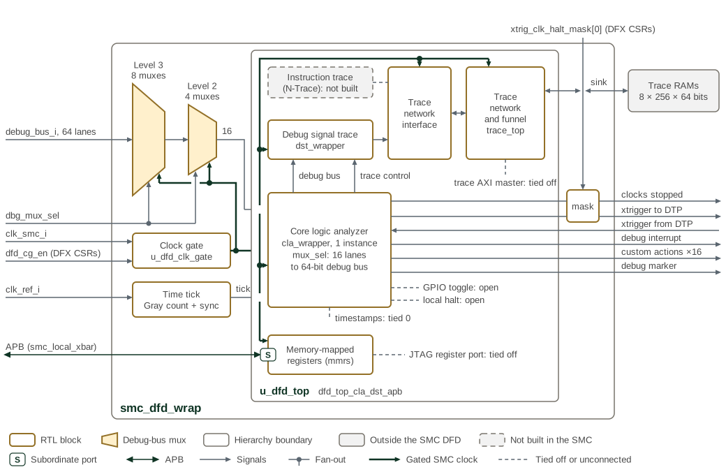
Figure 1 shows the DFD block as SMC instantiates it. smc_dfd_wrap
contains the DFD IP dfd_top_cla_dst_apb (u_dfd_top), configured with one
CLA and one debug signal trace (DST) instance. Parts of the generic block
that SMC does not build are drawn as dashed grey boxes. Inputs and outputs
that SMC ties off or leaves unconnected are drawn as dashed lines. The
instruction trace (N-Trace) is not built. The trace AXI master and the JTAG
register port are tied off, and the timestamp inputs are tied to zero.
The CLA and DST paths provide the observation functions described here.
The debug bus from smc_base has 64 lanes of 16 bits. Eight level-3 and
four level-2 debug-bus muxes reduce it to the 16 lanes that enter the CLA,
under the select register in the DFX CSRs. The CLA’s own mux stage then
selects the 64-bit debug bus that the CLA evaluates and passes to the DST.
The wrapper gates clk_smc_i for the muxes and the IP under dfd_cg_en,
and it counts clk_ref_i edges into the CLA time tick. The trace sink
writes eight external trace RAMs of 256 × 64 bits, 16 KiB in total.
Software programs the mux tree one mux at a time through the single
DEBUG_BUS_MUX register. The level-3 muxes have IDs 7 to 14 and each takes
eight consecutive debug-bus lanes; the level-2 muxes have IDs 3 to 6 and each
drives four consecutive CLA input lanes. A mux takes Dbmmode while Dbmid
equals its ID, and its lane selects while Dbmid equals its ID and its mode
is 1. Each lane select is a binary index: 0 passes input lane n to output
lane n, and 1 to 4 select input lanes 4 to 7. The CLA’s own stage,
programmed through CDbgMuxSelLo with DbmId 0, decodes its selects the
same way, so 1 to 12 select CLA input lanes 4 to 15. The
capture set-up sequence
is in the Programmer’s Guide.
Bit 0 of xtrig_clk_halt_mask in the DFX CSRs masks the CLA cross-trigger
and halt-clock outputs, with every cross-trigger lane masked together; bits
15:1 have no effect. The clocks-stopped output also requires
tdr_dbg_ctrl_clock_stop_en_i, and it drives a CPU interrupt and a DTP
clock-stop request. The debug interrupt drives a CPU interrupt. The sixteen
custom actions leave the SMC, and the SMU wires five of them to the SEP CPU
debug controls. The CLA debug marker returns to the SMC debug bus. The
debug_marker, chiplet_enable, gpio_en, dtb_ns_en and dtb_ew_en
fields of DEBUG_CTRL have no effect in SMC.
Key features include:
-
A programmable debug bus that routes internal signals of interest to the analyzer under software control
-
An event engine supporting signal-match, edge, transition, ones-count, any-change, and counter events
-
Event-action pairing that binds detected events to system actions
-
Per-trigger snapshot of the debug bus and status flags identifying which pair fired
-
Cross-trigger exchange with the rest of the debug infrastructure
-
Trace capture through the external sink-memory interface
1. Debug Bus
The analyzer operates on a debug bus: a fixed-width vector of internal signals sampled every cycle. A selection fabric chooses which internal signals are driven onto the bus, so a single analyzer can be pointed at different parts of the design without RTL changes. Software selects the observed signal set, then programs the event engine against the resulting bus value.
2. Core Logic Analyzer
The CLA is organized as a set of nodes, each holding several event-action pairs (EAPs). An EAP binds one or more events, computed from the debug bus, to one or more actions taken when those events occur. The event engine evaluates several event types in parallel (Table 1).
| Event | Description |
|---|---|
Signal match |
Fires when the masked debug bus equals a programmed value
( |
Edge |
Fires on a rising or falling edge of selected debug-bus signals. |
Transition |
Fires when a masked subset of the bus moves from a programmed value A to a programmed value B. |
Ones count |
Fires when the population count of a masked subset equals a programmed value. |
Any change |
Fires when any signal within a masked subset changes. |
Time match |
Unavailable in this integration. Its timestamp input is tied to zero. The comparator requires a nonzero match value, so the event cannot fire; it does not use the local CLA timestamp register. |
Counter |
Counts cycles following an event match and fires when the count is reached; a small pool of counters is available for measuring intervals or deferring an action. |
When an EAP fires, a status flag records which pair triggered — for example, so an interrupt handler can identify the source — and a snapshot register latches the debug-bus value at the moment of the trigger for post-mortem inspection. EAPs are enabled together once programming is complete, so a partially programmed pairing never triggers.
3. Actions and Cross-Triggering
An EAP can drive one or more actions:
-
Debug interrupt — raise the CLA interrupt, an ordinary maskable PLIC source (see Interrupts below).
-
Clock stop — halt clocks to freeze the design for inspection.
-
GPIO toggle — the generic block provides this action, but SMC terminates it on an unused local signal; it does not drive a pad.
-
Cross-trigger out — signal other debug blocks that a local event occurred.
-
Trace capture — hand the event to the trace subsystem.
-
Custom actions — reserved outputs for design-specific use.
Cross-trigger inputs let events elsewhere in the system arm or fire local actions, and cross-trigger outputs propagate local events outward, so debug conditions can be correlated across blocks rather than observed in isolation.
4. Trace
The configured trace sink uses external memory request/response ports. The optional trace AXI master has unconnected request outputs and tied-low response inputs, so it cannot stream trace over the SMC fabric.
SMC selects local CLA timestamp scheme 0, advanced by the wrapper’s reference
clock-derived time_tick. This local counter is distinct from the generic
i_timestamp, reference timestamp, and OCTS timestamp inputs, all tied to zero.
The integration does not provide the advertised global timestamp alignment
through those inputs. In particular, the time-match event consumes the tied-off
timestamp rather than the running CLA timestamp register.
Because of timestamp scheme 0 and the 64-bit CLA debug bus, several CLA
registers have no effect in SMC. TsCapture, CDbgTimestampCapture and
CDbgClaTimestampOffset serve only the reference-timestamp scheme. The Hi
halves of the match, compare, transition, ones-count, change and snapshot
registers serve only a 128-bit debug bus. CDbgMuxSelHi, and Muxselseg4
to Muxselseg7 of CDbgMuxSelLo, select lanes beyond the four that the CLA
mux drives.
5. Interrupts
The SMC interrupt table lists the two CLA-driven sources. See Interrupts.
-
CLA clock stop — asserted while the CLA has stopped clocks.
-
CLA debug interrupt — the debug interrupt raised by a CLA action.
6. Memory Map and Register Reference
6.1. Memory Map
The CLA counter values and timestamp fields are software-writable. Software
writes take priority over simultaneous hardware updates; later hardware updates
can advance or clear them according to their configured controls. The sink’s
trDstRamWPHigh register likewise accepts software writes. These are live
read/write state, not read-only status.
The generated smc_cla map is the programmer view of this aperture (see
Memory Map
).
6.2. Detailed Register Map
SMC DFD MMR Aperture Address Map
Composite debug (DFD) MMR aperture mapping the DST sink, funnel, CLA, and DST blocks that smc_dfd_wrap instantiates.
Register List:
| Address | Name | Access | Description |
|---|---|---|---|
| 0x0 | Trdstramcontrol | RW | - |
| 0x4 | Trdstramimpl | RW | - |
| 0x10 | Trdstramstartlow | RW | - |
| 0x14 | Trdstramstarthigh | RW | - |
| 0x18 | Trdstramlimitlow | RW | - |
| 0x1C | Trdstramlimithigh | RW | - |
| 0x20 | Trdstramwplow | RW | - |
| 0x24 | Trdstramwphigh | RW | - |
| 0x28 | Trdstramrplow | RW | - |
| 0x2C | Trdstramrphigh | RW | - |
| 0x40 | Trdstramdata | R | - |
| 0xFF8 | dst_sink.ScratchLo | RW | Scratch register (low) for DV and potential ECO usage |
| 0xFFC | dst_sink.ScratchHi | RW | Scratch register (high) for DV and potential ECO usage |
| 0x1000 | Trfunnelcontrol | RW | - |
| 0x1004 | Trfunnelimpl | R | - |
| 0x1008 | Trfunneldisinput | RW | - |
| 0x1FF8 | funnel.ScratchLo | RW | Scratch register (low) for DV and potential ECO usage |
| 0x1FFC | funnel.ScratchHi | RW | Scratch register (high) for DV and potential ECO usage |
| 0x2100 | CDbgClaCounter0Cfg | RW | Configure CLA counter0. One of the 4 counters used for counting cycles after a event match, and trigger a action on match. |
| 0x2108 | CDbgClaCounter1Cfg | RW | Configure CLA counter1. One of the 4 counters used for counting cycles after a event match, and trigger a action on match. |
| 0x2110 | CDbgClaCounter2Cfg | RW | Configure CLA counter2. One of the 4 counters used for counting cycles after a event match, and trigger a action on match. |
| 0x2118 | CDbgClaCounter3Cfg | RW | Configure CLA counter3. One of the 4 counters used for counting cycles after a event match, and trigger a action on match. |
| 0x2120 | CDbgNode0Eap0 | RW | CLA Action(s) are tied to events(s) using "event-action pairing" registers. One of the 16 EAPs (4 EAPs per Node, 4 Nodes). |
| 0x2128 | CDbgNode0Eap1 | RW | CLA Action(s) are tied to events(s) using "event-action pairing" registers. One of the 16 EAPs (4 EAPs per Node, 4 Nodes). |
| 0x2130 | CDbgNode1Eap0 | RW | CLA Action(s) are tied to events(s) using "event-action pairing" registers. One of the 16 EAPs (4 EAPs per Node, 4 Nodes). |
| 0x2138 | CDbgNode1Eap1 | RW | CLA Action(s) are tied to events(s) using "event-action pairing" registers. One of the 16 EAPs (4 EAPs per Node, 4 Nodes). |
| 0x2140 | CDbgNode2Eap0 | RW | CLA Action(s) are tied to events(s) using "event-action pairing" registers. One of the 16 EAPs (4 EAPs per Node, 4 Nodes). |
| 0x2148 | CDbgNode2Eap1 | RW | CLA Action(s) are tied to events(s) using "event-action pairing" registers. One of the 16 EAPs (4 EAPs per Node, 4 Nodes). |
| 0x2150 | CDbgNode3Eap0 | RW | CLA Action(s) are tied to events(s) using "event-action pairing" registers. One of the 16 EAPs (4 EAPs per Node, 4 Nodes). |
| 0x2158 | CDbgNode3Eap1 | RW | CLA Action(s) are tied to events(s) using "event-action pairing" registers. One of the 16 EAPs (4 EAPs per Node, 4 Nodes). |
| 0x2160 | CDbgSignalMask0Lo | RW | Used to define debug bus match events. The positive match event (0x2) fires when debug_bus & mask = match; the negative match event (0x3) fires when debug_bus & mask != match. |
| 0x2168 | CDbgSignalMatch0Lo | RW | Used to define debug bus match events. The positive match event (0x2) fires when debug_bus & mask = match; the negative match event (0x3) fires when debug_bus & mask != match. |
| 0x2170 | CDbgSignalMask1Lo | RW | Used to define debug bus match events. The positive match event (0x4) fires when debug_bus & mask = match; the negative match event (0x5) fires when debug_bus & mask != match. |
| 0x2178 | CDbgSignalMatch1Lo | RW | Used to define debug bus match events. The positive match event (0x4) fires when debug_bus & mask = match; the negative match event (0x5) fires when debug_bus & mask != match. |
| 0x2180 | CDbgSignalEdgeDetectCfg | RW | Register to configure debug bus for edge triggers. |
| 0x2188 | CDbgEapStatus | RW | Register to indicate if an EAP was activated. There is one status bit per EAP in bits [15:0] (Node0Eap0..Node3Eap3, 4 EAPs per Node across 4 Nodes) and one write-to-clear bit per EAP in bits [47:32] (Node0Eap0W2C..Node3Eap3W2C); write the matching w2c bit to reset a status bit. The register is used by SW to know if an action was taken (ex: NMI ISR needs to know which of the EAP triggered the NMI) |
| 0x2190 | CDbgClaCtrlStatus | RW | Ctrl/Status register to Enable EAP after EAP programming is complete, and read the current node. |
| 0x2198 | CDbgMuxSelLo | RW | Mode, ID, fine-grain time enable and lane selects for the CLA debug-bus mux, which builds the four 16-bit lanes of the CLA's 64-bit debug bus from 16 input segments. The mux ID is 0: the mode is taken while DbmId is 0, and the lane selects while DbmId is 0 and DbmMode is 1. |
| 0x21A0 | CDbgRsvd1 | RW | Reserved Register that can be changed. |
| 0x21A8 | CDbgRsvd2 | RW | Reserved Register that can be changed. |
| 0x21B0 | CDbgTransitionMaskLo | RW | 3 registers to configure "transition event". This register is to select the signals of interest using a mask. |
| 0x21B8 | CDbgTransitionFromValueLo | RW | 3 registers to configure "transition event". The event is triggered on transition from Value A to Value B. This register specifies Value A. |
| 0x21C0 | CDbgTransitionToValueLo | RW | 3 registers to configure "transition event". The event is triggered on transition from Value A to Value B. This register specifies Value B. |
| 0x21C8 | CDbgOnesCountMaskLo | RW | 2 registers to configure "ones count" event. This register is to select the signals of interest using a mask. |
| 0x21D0 | CDbgOnesCountValue | RW | 2 registers to configure "ones count" event. Event triggered when the sum of the signals match the value specified in this register. |
| 0x21D8 | CDbgAnyChangeLo | RW | Event triggered when a subset of debug signals change. The mask is used to select the subset of the debug signals. |
| 0x21E0 | CDbgSignalSnapshotNode0Eap0Lo | R | debug Bus Value when Node0 Eap0 Trigger is met. |
| 0x21E8 | CDbgSignalSnapshotNode0Eap1Lo | R | debug Bus Value when Node0 Eap1 Trigger is met. |
| 0x21F0 | CDbgSignalSnapshotNode1Eap0Lo | R | debug Bus Value when Node1 Eap0 Trigger is met. |
| 0x21F8 | CDbgSignalSnapshotNode1Eap1Lo | R | debug Bus Value when Node1 Eap1 Trigger is met. |
| 0x2200 | CDbgSignalSnapshotNode2Eap0Lo | R | debug Bus Value when Node2 Eap0 Trigger is met. |
| 0x2208 | CDbgSignalSnapshotNode2Eap1Lo | R | debug Bus Value when Node2 Eap1 Trigger is met. |
| 0x2210 | CDbgSignalSnapshotNode3Eap0Lo | R | debug Bus Value when Node3 Eap0 Trigger is met. |
| 0x2218 | CDbgSignalSnapshotNode3Eap1Lo | R | debug Bus Value when Node3 Eap1 Trigger is met. |
| 0x2220 | CDbgClaTimeMatch | RW | This value is compared (greater than or equal to the programmed value) against the internal time register value of the core, and is used to generate a time match event for CLA. Needs to be non zero for the time match event signal to trigger. The event will only trigger an action if the EAP programming is done. Requires writing 0 to this register to stop the match event. |
| 0x2228 | CDbgSignalMask2Lo | RW | Used to define debug bus match events. The positive match event (0x1C) fires when debug_bus & mask = match; the negative match event (0x1D) fires when debug_bus & mask != match. |
| 0x2230 | CDbgSignalMatch2Lo | RW | Used to define debug bus match events. The positive match event (0x1C) fires when debug_bus & mask = match; the negative match event (0x1D) fires when debug_bus & mask != match. |
| 0x2238 | CDbgSignalMask3Lo | RW | Used to define debug bus match events. The positive match event (0x1E) fires when debug_bus & mask = match; the negative match event (0x1F) fires when debug_bus & mask != match. |
| 0x2240 | CDbgSignalMatch3Lo | RW | Used to define debug bus match events. The positive match event (0x1E) fires when debug_bus & mask = match; the negative match event (0x1F) fires when debug_bus & mask != match. |
| 0x2248 | CDbgNode0Eap2 | RW | CLA Action(s) are tied to events(s) using "event-action pairing" registers. One of the 16 EAPs (4 EAPs per Node, 4 Nodes). |
| 0x2250 | CDbgNode0Eap3 | RW | CLA Action(s) are tied to events(s) using "event-action pairing" registers. One of the 16 EAPs (4 EAPs per Node, 4 Nodes). |
| 0x2258 | CDbgNode1Eap2 | RW | CLA Action(s) are tied to events(s) using "event-action pairing" registers. One of the 16 EAPs (4 EAPs per Node, 4 Nodes). |
| 0x2260 | CDbgNode1Eap3 | RW | CLA Action(s) are tied to events(s) using "event-action pairing" registers. One of the 16 EAPs (4 EAPs per Node, 4 Nodes). |
| 0x2268 | CDbgNode2Eap2 | RW | CLA Action(s) are tied to events(s) using "event-action pairing" registers. One of the 16 EAPs (4 EAPs per Node, 4 Nodes). |
| 0x2270 | CDbgNode2Eap3 | RW | CLA Action(s) are tied to events(s) using "event-action pairing" registers. One of the 16 EAPs (4 EAPs per Node, 4 Nodes). |
| 0x2278 | CDbgNode3Eap2 | RW | CLA Action(s) are tied to events(s) using "event-action pairing" registers. One of the 16 EAPs (4 EAPs per Node, 4 Nodes). |
| 0x2280 | CDbgNode3Eap3 | RW | CLA Action(s) are tied to events(s) using "event-action pairing" registers. One of the 16 EAPs (4 EAPs per Node, 4 Nodes). |
| 0x2288 | CDbgSignalSnapshotNode0Eap2Lo | R | debug Bus Value when Node0 Eap2 Trigger is met. |
| 0x2290 | CDbgSignalSnapshotNode0Eap3Lo | R | debug Bus Value when Node0 Eap3 Trigger is met. |
| 0x2298 | CDbgSignalSnapshotNode1Eap2Lo | R | debug Bus Value when Node1 Eap2 Trigger is met. |
| 0x22A0 | CDbgSignalSnapshotNode1Eap3Lo | R | debug Bus Value when Node1 Eap3 Trigger is met. |
| 0x22A8 | CDbgSignalSnapshotNode2Eap2Lo | R | debug Bus Value when Node2 Eap2 Trigger is met. |
| 0x22B0 | CDbgSignalSnapshotNode2Eap3Lo | R | debug Bus Value when Node2 Eap3 Trigger is met. |
| 0x22B8 | CDbgSignalSnapshotNode3Eap2Lo | R | debug Bus Value when Node3 Eap2 Trigger is met. |
| 0x22C0 | CDbgSignalSnapshotNode3Eap3Lo | R | debug Bus Value when Node3 Eap3 Trigger is met. |
| 0x22C8 | CDbgSignalDelayMuxSel | RW | - |
| 0x22D8 | CDbgClaXtriggerTimestretch | RW | This value determines the time stretched pulse duration for the cross trigger. 8 bits for each of the two triggers. |
| 0x22F0 | CDbgClaTimestamp | RW | 64-bit timestamp counter. Increments on time_tick. Can be written directly or loaded from timestamp_sync on xtrigger when resync is enabled. |
| 0x22F8 | CDbgClaTimestampSync | RW | Timestamp sync value. This value is loaded into the timestamp register on xtrigger posedge when resync bit is enabled. |
| 0x2300 | CDbgClaTimestampConfig | RW | Timestamp configuration register. Controls resync behavior and debug marker. |
| 0x2308 | CDbgClaTimestampOffset | RW | Timestamp offset register. The Offset value is subtracted from the timestamp before comparing with incoming timestamp value. No effect in the SMC, where the CLA timestamp counts the local time tick (timestamp scheme 0). |
| 0x2400 | CDbgSignalMask0Hi | RW | Used to define debug bus match events. The positive match event (0x2) fires when debug_bus & mask = match; the negative match event (0x3) fires when debug_bus & mask != match. No effect in the SMC, whose CLA evaluates a 64-bit debug bus; only the Lo register is used. |
| 0x2408 | CDbgSignalMatch0Hi | RW | Used to define debug bus match events. The positive match event (0x2) fires when debug_bus & mask = match; the negative match event (0x3) fires when debug_bus & mask != match. No effect in the SMC, whose CLA evaluates a 64-bit debug bus; only the Lo register is used. |
| 0x2410 | CDbgSignalMask1Hi | RW | Used to define debug bus match events. The positive match event (0x4) fires when debug_bus & mask = match; the negative match event (0x5) fires when debug_bus & mask != match. No effect in the SMC, whose CLA evaluates a 64-bit debug bus; only the Lo register is used. |
| 0x2418 | CDbgSignalMatch1Hi | RW | Used to define debug bus match events. The positive match event (0x4) fires when debug_bus & mask = match; the negative match event (0x5) fires when debug_bus & mask != match. No effect in the SMC, whose CLA evaluates a 64-bit debug bus; only the Lo register is used. |
| 0x2420 | CDbgSignalMask2Hi | RW | Used to define debug bus match events. The positive match event (0x1C) fires when debug_bus & mask = match; the negative match event (0x1D) fires when debug_bus & mask != match. No effect in the SMC, whose CLA evaluates a 64-bit debug bus; only the Lo register is used. |
| 0x2428 | CDbgSignalMatch2Hi | RW | Used to define debug bus match events. The positive match event (0x1C) fires when debug_bus & mask = match; the negative match event (0x1D) fires when debug_bus & mask != match. No effect in the SMC, whose CLA evaluates a 64-bit debug bus; only the Lo register is used. |
| 0x2430 | CDbgSignalMask3Hi | RW | Used to define debug bus match events. The positive match event (0x1E) fires when debug_bus & mask = match; the negative match event (0x1F) fires when debug_bus & mask != match. No effect in the SMC, whose CLA evaluates a 64-bit debug bus; only the Lo register is used. |
| 0x2438 | CDbgSignalMatch3Hi | RW | Used to define debug bus match events. The positive match event (0x1E) fires when debug_bus & mask = match; the negative match event (0x1F) fires when debug_bus & mask != match. No effect in the SMC, whose CLA evaluates a 64-bit debug bus; only the Lo register is used. |
| 0x2440 | CDbgMuxSelHi | RW | No effect in the SMC. The CLA debug-bus mux has four output lanes and takes its mode, ID, fine-grain time enable and lane selects from CDbgMuxSelLo. |
| 0x2448 | CDbgTransitionMaskHi | RW | 3 registers to configure "transition event". This register is to select the signals of interest using a mask. No effect in the SMC, whose CLA evaluates a 64-bit debug bus; only the Lo register is used. |
| 0x2450 | CDbgTransitionFromValueHi | RW | 3 registers to configure "transition event". The event is triggered on transition from Value A to Value B. This register specifies Value A. No effect in the SMC, whose CLA evaluates a 64-bit debug bus; only the Lo register is used. |
| 0x2458 | CDbgTransitionToValueHi | RW | 3 registers to configure "transition event". The event is triggered on transition from Value A to Value B. This register specifies Value B. No effect in the SMC, whose CLA evaluates a 64-bit debug bus; only the Lo register is used. |
| 0x2460 | CDbgOnesCountMaskHi | RW | 2 registers to configure "ones count" event. This register is to select the signals of interest using a mask. No effect in the SMC, whose CLA evaluates a 64-bit debug bus; only the Lo register is used. |
| 0x2468 | CDbgAnyChangeHi | RW | Event triggered when a subset of debug signals change. The mask is used to select the subset of the debug signals. No effect in the SMC, whose CLA evaluates a 64-bit debug bus; only the Lo register is used. |
| 0x2470 | CDbgSignalSnapshotNode0Eap0Hi | R | debug Bus Value when Node0 Eap0 Trigger is met. Never captured in the SMC, whose CLA evaluates a 64-bit debug bus. |
| 0x2478 | CDbgSignalSnapshotNode0Eap1Hi | R | debug Bus Value when Node0 Eap1 Trigger is met. Never captured in the SMC, whose CLA evaluates a 64-bit debug bus. |
| 0x2480 | CDbgSignalSnapshotNode1Eap0Hi | R | debug Bus Value when Node1 Eap0 Trigger is met. Never captured in the SMC, whose CLA evaluates a 64-bit debug bus. |
| 0x2488 | CDbgSignalSnapshotNode1Eap1Hi | R | debug Bus Value when Node1 Eap1 Trigger is met. Never captured in the SMC, whose CLA evaluates a 64-bit debug bus. |
| 0x2490 | CDbgSignalSnapshotNode2Eap0Hi | R | debug Bus Value when Node2 Eap0 Trigger is met. Never captured in the SMC, whose CLA evaluates a 64-bit debug bus. |
| 0x2498 | CDbgSignalSnapshotNode2Eap1Hi | R | debug Bus Value when Node2 Eap1 Trigger is met. Never captured in the SMC, whose CLA evaluates a 64-bit debug bus. |
| 0x24A0 | CDbgSignalSnapshotNode3Eap0Hi | R | debug Bus Value when Node3 Eap0 Trigger is met. Never captured in the SMC, whose CLA evaluates a 64-bit debug bus. |
| 0x24A8 | CDbgSignalSnapshotNode3Eap1Hi | R | debug Bus Value when Node3 Eap1 Trigger is met. Never captured in the SMC, whose CLA evaluates a 64-bit debug bus. |
| 0x24B0 | CDbgSignalSnapshotNode0Eap2Hi | R | debug Bus Value when Node0 Eap2 Trigger is met. Never captured in the SMC, whose CLA evaluates a 64-bit debug bus. |
| 0x24B8 | CDbgSignalSnapshotNode0Eap3Hi | R | debug Bus Value when Node0 Eap3 Trigger is met. Never captured in the SMC, whose CLA evaluates a 64-bit debug bus. |
| 0x24C0 | CDbgSignalSnapshotNode1Eap2Hi | R | debug Bus Value when Node1 Eap2 Trigger is met. Never captured in the SMC, whose CLA evaluates a 64-bit debug bus. |
| 0x24C8 | CDbgSignalSnapshotNode1Eap3Hi | R | debug Bus Value when Node1 Eap3 Trigger is met. Never captured in the SMC, whose CLA evaluates a 64-bit debug bus. |
| 0x24D0 | CDbgSignalSnapshotNode2Eap2Hi | R | debug Bus Value when Node2 Eap2 Trigger is met. Never captured in the SMC, whose CLA evaluates a 64-bit debug bus. |
| 0x24D8 | CDbgSignalSnapshotNode2Eap3Hi | R | debug Bus Value when Node2 Eap3 Trigger is met. Never captured in the SMC, whose CLA evaluates a 64-bit debug bus. |
| 0x24E0 | CDbgSignalSnapshotNode3Eap2Hi | R | debug Bus Value when Node3 Eap2 Trigger is met. Never captured in the SMC, whose CLA evaluates a 64-bit debug bus. |
| 0x24E8 | CDbgSignalSnapshotNode3Eap3Hi | R | debug Bus Value when Node3 Eap3 Trigger is met. Never captured in the SMC, whose CLA evaluates a 64-bit debug bus. |
| 0x24F0 | CDbgLfsr | RW | LFSR value. |
| 0x24F8 | CDbgLfsrMask | RW | LFSR programming mask. |
| 0x2500 | CDbgTimestampCapture | R | Captured timestamp upper bits. When ts_capture is set in the timestamp config register, a cross trigger 0 event captures the timestamp upper bits into this register. Never captured in the SMC, where the CLA timestamp counts the local time tick (timestamp scheme 0). |
| 0x2508 | CDbgCompare0Lo | RW | Value for arithmetic comparison. |
| 0x2510 | CDbgCompare0MaskLo | RW | Value to mask the arithmetic comparison. |
| 0x2518 | CDbgCompare1Lo | RW | Value for arithmetic comparison. |
| 0x2520 | CDbgCompare1MaskLo | RW | Value to mask the arithmetic comparison. |
| 0x2528 | CDbgCompare2Lo | RW | Value for arithmetic comparison. |
| 0x2530 | CDbgCompare2MaskLo | RW | Value to mask the arithmetic comparison. |
| 0x2538 | CDbgCompare3Lo | RW | Value for arithmetic comparison. |
| 0x2540 | CDbgCompare3MaskLo | RW | Value to mask the arithmetic comparison. |
| 0x2548 | CDbgCompare0Hi | RW | Value for arithmetic comparison. No effect in the SMC, whose CLA evaluates a 64-bit debug bus; only the Lo register is used. |
| 0x2550 | CDbgCompare0MaskHi | RW | Value to mask the arithmetic comparison. No effect in the SMC, whose CLA evaluates a 64-bit debug bus; only the Lo register is used. |
| 0x2558 | CDbgCompare1Hi | RW | Value for arithmetic comparison. No effect in the SMC, whose CLA evaluates a 64-bit debug bus; only the Lo register is used. |
| 0x2560 | CDbgCompare1MaskHi | RW | Value to mask the arithmetic comparison. No effect in the SMC, whose CLA evaluates a 64-bit debug bus; only the Lo register is used. |
| 0x2568 | CDbgCompare2Hi | RW | Value for arithmetic comparison. No effect in the SMC, whose CLA evaluates a 64-bit debug bus; only the Lo register is used. |
| 0x2570 | CDbgCompare2MaskHi | RW | Value to mask the arithmetic comparison. No effect in the SMC, whose CLA evaluates a 64-bit debug bus; only the Lo register is used. |
| 0x2578 | CDbgCompare3Hi | RW | Value for arithmetic comparison. No effect in the SMC, whose CLA evaluates a 64-bit debug bus; only the Lo register is used. |
| 0x2580 | CDbgCompare3MaskHi | RW | Value to mask the arithmetic comparison. No effect in the SMC, whose CLA evaluates a 64-bit debug bus; only the Lo register is used. |
| 0x2FF8 | Scratch | RW | Additional scratch register for DV and potential ECO usage |
| 0x3000 | Trdstcontrol | RW | - |
| 0x3004 | Trdstimpl | RW | - |
| 0x3008 | Trdstinstfeatures | RW | - |
| 0x31A0 | CDbgDebugTraceCfg | RW | - |
| 0x3FF8 | dst.ScratchLo | RW | Scratch register (low) for DV and potential ECO usage |
| 0x3FFC | dst.ScratchHi | RW | Scratch register (high) for DV and potential ECO usage |
Register Details:
Trdstramcontrol
| Bits | Field | Access | Reset | Description |
|---|---|---|---|---|
| 31:9 | Reserved | - | - | Reserved |
| 8 | Trdstramstoponwrap | RW | 0x0 | - |
| 7:5 | Reserved | - | - | Reserved |
| 4 | Trdstrammode | RW | 0x0 | - |
| 3 | Trdstramempty | R | 0x1 | - |
| 2 | Reserved | - | - | Reserved |
| 1 | Trdstramenable | RW | 0x0 | - |
| 0 | Trdstramactive | RW | 0x0 | - |
Trdstramimpl
| Bits | Field | Access | Reset | Description |
|---|---|---|---|---|
| 31:28 | Reserved | - | - | Reserved |
| 27:24 | Trdstramvendorframelength | RW | 0x1 | Frame length in 64-byte units. Only 1, 2, 4 and 8 (64, 128, 256 and 512 bytes) are supported, and the value must match the DST's trDstVendorFrameLength. |
| 23:14 | Reserved | - | - | Reserved |
| 13 | Trdstramhassmem | R | 0x1 | - |
| 12 | Trdstramhassram | R | 0x1 | - |
| 11:8 | Trdstramcomptype | R | 0x9 | - |
| 7:4 | Trdstramverminor | R | 0x0 | - |
| 3:0 | Trdstramvermajor | R | 0x1 | - |
Trdstramstartlow
| Bits | Field | Access | Reset | Description |
|---|---|---|---|---|
| 31:2 | Trdstramstartlow | RW | 0x0 | - |
| 1:0 | Rsvd10 | R | 0x0 | - |
Trdstramstarthigh
| Bits | Field | Access | Reset | Description |
|---|---|---|---|---|
| 31:0 | Trdstramstarthigh | RW | 0x0 | - |
Trdstramlimitlow
| Bits | Field | Access | Reset | Description |
|---|---|---|---|---|
| 31:2 | Trdstramlimitlow | RW | 0x0 | - |
| 1:0 | Rsvd10 | R | 0x0 | - |
Trdstramlimithigh
| Bits | Field | Access | Reset | Description |
|---|---|---|---|---|
| 31:0 | Trdstramlimithigh | RW | 0x0 | - |
Trdstramwplow
| Bits | Field | Access | Reset | Description |
|---|---|---|---|---|
| 31:2 | Trdstramwplow | RW | 0x0 | - |
| 1 | Reserved | - | - | Reserved |
| 0 | Trdstramwrap | R | 0x0 | - |
Trdstramwphigh
| Bits | Field | Access | Reset | Description |
|---|---|---|---|---|
| 31:0 | Trdstramwphigh | RW | 0x0 | - |
Trdstramrplow
| Bits | Field | Access | Reset | Description |
|---|---|---|---|---|
| 31:2 | Trdstramrplow | RW | 0x0 | Read pointer, in 32-bit words; bits [31:2] of the byte address of the word the next trDstRamData read returns. Each trDstRamData read that returns unread data advances it by one word, and from trDstRamLimitLow it wraps to trDstRamStartLow. |
| 1:0 | Rsvd10 | R | 0x0 | - |
Trdstramrphigh
| Bits | Field | Access | Reset | Description |
|---|---|---|---|---|
| 31:0 | Trdstramrphigh | RW | 0x0 | - |
Trdstramdata
| Bits | Field | Access | Reset | Description |
|---|---|---|---|---|
| 31:0 | Trdstramdata | R | 0x0 | Reading launches a trace-RAM read at trDstRamRPLow. When the RAM holds unread data, the read returns that 32-bit word and advances trDstRamRPLow; otherwise the pointer does not move. |
dst_sink.ScratchLo
| Bits | Field | Access | Reset | Description |
|---|---|---|---|---|
| 31:0 | Data | RW | 0x0 | - |
dst_sink.ScratchHi
| Bits | Field | Access | Reset | Description |
|---|---|---|---|---|
| 31:0 | Data | RW | 0x0 | - |
Trfunnelcontrol
| Bits | Field | Access | Reset | Description |
|---|---|---|---|---|
| 31:4 | Reserved | - | - | Reserved |
| 3 | Trfunnelempty | R | 0x1 | - |
| 2 | Reserved | - | - | Reserved |
| 1 | Trfunnelenable | RW | 0x0 | - |
| 0 | Trfunnelactive | RW | 0x0 | - |
Trfunnelimpl
| Bits | Field | Access | Reset | Description |
|---|---|---|---|---|
| 31:12 | Reserved | - | - | Reserved |
| 11:8 | Trfunnelcomptype | R | 0x8 | - |
| 7:4 | Trfunnelverminor | R | 0x0 | e |
| 3:0 | Trfunnelvermajor | R | 0x1 | - |
Trfunneldisinput
| Bits | Field | Access | Reset | Description |
|---|---|---|---|---|
| 31:16 | Reserved | - | - | Reserved |
| 15:0 | Trfunneldisinput | RW | 0x0 | Bits 7:0 are reserved for N-trace srcs and 15:8 for Dst sources |
funnel.ScratchLo
| Bits | Field | Access | Reset | Description |
|---|---|---|---|---|
| 31:0 | Data | RW | 0x0 | - |
funnel.ScratchHi
| Bits | Field | Access | Reset | Description |
|---|---|---|---|---|
| 31:0 | Data | RW | 0x0 | - |
CDbgClaCounter0Cfg
| Bits | Field | Access | Reset | Description |
|---|---|---|---|---|
| 63 | Rsvd | RW | 0x0 | - |
| 62:48 | UpperTarget | RW | 0x0 | - |
| 47:33 | UpperCounter | RW | 0x0 | - |
| 32 | ResetOnTarget | RW | 0x0 | When Counter = {upper_target,target} reset to 0. With this bit set, counter will provide a periodic tick w/ frequency of (target +1) if the action is set to Auto Incr. The periodic tick will continue till Stop Auto Incr or Clear Counter action. |
| 31:16 | Target | RW | 0x0 | - |
| 15:0 | Counter | RW | 0x0 | - |
CDbgClaCounter1Cfg
| Bits | Field | Access | Reset | Description |
|---|---|---|---|---|
| 63 | Rsvd | RW | 0x0 | - |
| 62:48 | UpperTarget | RW | 0x0 | - |
| 47:33 | UpperCounter | RW | 0x0 | - |
| 32 | ResetOnTarget | RW | 0x0 | When Counter = {upper_target,target}, reset to 0. With this bit set, counter will provide a periodic tick w/ frequency of (target +1) if the action is set to Auto Incr. The periodic tick will continue till Stop Auto Incr or Clear Counter action. |
| 31:16 | Target | RW | 0x0 | - |
| 15:0 | Counter | RW | 0x0 | - |
CDbgClaCounter2Cfg
| Bits | Field | Access | Reset | Description |
|---|---|---|---|---|
| 63 | Rsvd | RW | 0x0 | - |
| 62:48 | UpperTarget | RW | 0x0 | - |
| 47:33 | UpperCounter | RW | 0x0 | - |
| 32 | ResetOnTarget | RW | 0x0 | When Counter = {upper_target,target}, reset to 0. With this bit set, counter will provide a periodic tick w/ frequency of (target +1) if the action is set to Auto Incr. The periodic tick will continue till Stop Auto Incr or Clear Counter action. |
| 31:16 | Target | RW | 0x0 | - |
| 15:0 | Counter | RW | 0x0 | - |
CDbgClaCounter3Cfg
| Bits | Field | Access | Reset | Description |
|---|---|---|---|---|
| 63 | Rsvd | RW | 0x0 | - |
| 62:48 | UpperTarget | RW | 0x0 | - |
| 47:33 | UpperCounter | RW | 0x0 | - |
| 32 | ResetOnTarget | RW | 0x0 | When Counter = {upper_target,target}, reset to 0. With this bit set, counter will provide a periodic tick w/ frequency of (target +1) if the action is set to Auto Incr. The periodic tick will continue till Stop Auto Incr or Clear Counter action. |
| 31:16 | Target | RW | 0x0 | - |
| 15:0 | Counter | RW | 0x0 | - |
CDbgNode0Eap0
| Bits | Field | Access | Reset | Description |
|---|---|---|---|---|
| 63:58 | Action3 | RW | 0x0 | Select an Action |
| 57:52 | Action2 | RW | 0x0 | Select an Action |
| 51:44 | Udf | RW | 0x0 | User Defined Function with event type 0, 1, and 2 as arguments |
| 43:38 | EventType2 | RW | 0x0 | Select a trigger event |
| 37 | CustomAction1Enable | RW | 0x0 | custom_action1 is valid only if custom_action1_enable is set |
| 36 | CustomAction0Enable | RW | 0x0 | custom_action0 is valid only if custom_action0_enable is set |
| 35:32 | CustomAction1 | RW | 0x0 | Select the bit position of custom action bus to be set when EAP trigger is met. External blocks can define and implement the specific action for a given bit. |
| 31:28 | CustomAction0 | RW | 0x0 | Select the bit position of custom action bus to be set when EAP trigger is met. External blocks can define and implement the specific action for a given bit. |
| 27:22 | EventType1 | RW | 0x0 | Select a trigger event |
| 21:16 | EventType0 | RW | 0x0 | Select a trigger event |
| 15:14 | LogicalOp | RW | 0x0 | Relation to be satisfied among events to activate the actions |
| 13:8 | Action1 | RW | 0x0 | Select an Action |
| 7:2 | Action0 | RW | 0x0 | Select an Action |
| 1:0 | DestNode | RW | 0x0 | Select Destination Node |
CDbgNode0Eap1
| Bits | Field | Access | Reset | Description |
|---|---|---|---|---|
| 63:58 | Action3 | RW | 0x0 | Select an Action |
| 57:52 | Action2 | RW | 0x0 | Select an Action |
| 51:44 | Udf | RW | 0x0 | User Defined Function with event type 0, 1, and 2 as arguments |
| 43:38 | EventType2 | RW | 0x0 | Select a trigger event |
| 37 | CustomAction1Enable | RW | 0x0 | custom_action1 is valid only if custom_action1_enable is set |
| 36 | CustomAction0Enable | RW | 0x0 | custom_action0 is valid only if custom_action0_enable is set |
| 35:32 | CustomAction1 | RW | 0x0 | Select the bit position of custom action bus to be set when EAP trigger is met. External blocks can define and implement the specific action for a given bit. |
| 31:28 | CustomAction0 | RW | 0x0 | Select the bit position of custom action bus to be set when EAP trigger is met. External blocks can define and implement the specific action for a given bit. |
| 27:22 | EventType1 | RW | 0x0 | Select a trigger event |
| 21:16 | EventType0 | RW | 0x0 | Select a trigger event |
| 15:14 | LogicalOp | RW | 0x0 | Relation to be satisfied among events to activate the actions |
| 13:8 | Action1 | RW | 0x0 | Select an Action |
| 7:2 | Action0 | RW | 0x0 | Select an Action |
| 1:0 | DestNode | RW | 0x0 | Select Destination Node |
CDbgNode1Eap0
| Bits | Field | Access | Reset | Description |
|---|---|---|---|---|
| 63:58 | Action3 | RW | 0x0 | Select an Action |
| 57:52 | Action2 | RW | 0x0 | Select an Action |
| 51:44 | Udf | RW | 0x0 | User Defined Function with event type 0, 1, and 2 as arguments |
| 43:38 | EventType2 | RW | 0x0 | Select a trigger event |
| 37 | CustomAction1Enable | RW | 0x0 | custom_action1 is valid only if custom_action1_enable is set |
| 36 | CustomAction0Enable | RW | 0x0 | custom_action0 is valid only if custom_action0_enable is set |
| 35:32 | CustomAction1 | RW | 0x0 | Select the bit position of custom action bus to be set when EAP trigger is met. External blocks can define and implement the specific action for a given bit. |
| 31:28 | CustomAction0 | RW | 0x0 | Select the bit position of custom action bus to be set when EAP trigger is met. External blocks can define and implement the specific action for a given bit. |
| 27:22 | EventType1 | RW | 0x0 | Select a trigger event |
| 21:16 | EventType0 | RW | 0x0 | Select a trigger event |
| 15:14 | LogicalOp | RW | 0x0 | Relation to be satisfied among events to activate the actions |
| 13:8 | Action1 | RW | 0x0 | Select an Action |
| 7:2 | Action0 | RW | 0x0 | Select an Action |
| 1:0 | DestNode | RW | 0x0 | Select Destination Node |
CDbgNode1Eap1
| Bits | Field | Access | Reset | Description |
|---|---|---|---|---|
| 63:58 | Action3 | RW | 0x0 | Select an Action |
| 57:52 | Action2 | RW | 0x0 | Select an Action |
| 51:44 | Udf | RW | 0x0 | User Defined Function with event type 0, 1, and 2 as arguments |
| 43:38 | EventType2 | RW | 0x0 | Select a trigger event |
| 37 | CustomAction1Enable | RW | 0x0 | custom_action1 is valid only if custom_action1_enable is set |
| 36 | CustomAction0Enable | RW | 0x0 | custom_action0 is valid only if custom_action0_enable is set |
| 35:32 | CustomAction1 | RW | 0x0 | Select the bit position of custom action bus to be set when EAP trigger is met. External blocks can define and implement the specific action for a given bit. |
| 31:28 | CustomAction0 | RW | 0x0 | Select the bit position of custom action bus to be set when EAP trigger is met. External blocks can define and implement the specific action for a given bit. |
| 27:22 | EventType1 | RW | 0x0 | Select a trigger event |
| 21:16 | EventType0 | RW | 0x0 | Select a trigger event |
| 15:14 | LogicalOp | RW | 0x0 | Relation to be satisfied among events to activate the actions |
| 13:8 | Action1 | RW | 0x0 | Select an Action |
| 7:2 | Action0 | RW | 0x0 | Select an Action |
| 1:0 | DestNode | RW | 0x0 | Select Destination Node |
CDbgNode2Eap0
| Bits | Field | Access | Reset | Description |
|---|---|---|---|---|
| 63:58 | Action3 | RW | 0x0 | Select an Action |
| 57:52 | Action2 | RW | 0x0 | Select an Action |
| 51:44 | Udf | RW | 0x0 | User Defined Function with event type 0, 1, and 2 as arguments |
| 43:38 | EventType2 | RW | 0x0 | Select a trigger event |
| 37 | CustomAction1Enable | RW | 0x0 | custom_action1 is valid only if custom_action1_enable is set |
| 36 | CustomAction0Enable | RW | 0x0 | custom_action0 is valid only if custom_action0_enable is set |
| 35:32 | CustomAction1 | RW | 0x0 | Select the bit position of custom action bus to be set when EAP trigger is met. External blocks can define and implement the specific action for a given bit. |
| 31:28 | CustomAction0 | RW | 0x0 | Select the bit position of custom action bus to be set when EAP trigger is met. External blocks can define and implement the specific action for a given bit. |
| 27:22 | EventType1 | RW | 0x0 | Select a trigger event |
| 21:16 | EventType0 | RW | 0x0 | Select a trigger event |
| 15:14 | LogicalOp | RW | 0x0 | Relation to be satisfied among events to activate the actions |
| 13:8 | Action1 | RW | 0x0 | Select an Action |
| 7:2 | Action0 | RW | 0x0 | Select an Action |
| 1:0 | DestNode | RW | 0x0 | Select Destination Node |
CDbgNode2Eap1
| Bits | Field | Access | Reset | Description |
|---|---|---|---|---|
| 63:58 | Action3 | RW | 0x0 | Select an Action |
| 57:52 | Action2 | RW | 0x0 | Select an Action |
| 51:44 | Udf | RW | 0x0 | User Defined Function with event type 0, 1, and 2 as arguments |
| 43:38 | EventType2 | RW | 0x0 | Select a trigger event |
| 37 | CustomAction1Enable | RW | 0x0 | custom_action1 is valid only if custom_action1_enable is set |
| 36 | CustomAction0Enable | RW | 0x0 | custom_action0 is valid only if custom_action0_enable is set |
| 35:32 | CustomAction1 | RW | 0x0 | Select the bit position of custom action bus to be set when EAP trigger is met. External blocks can define and implement the specific action for a given bit. |
| 31:28 | CustomAction0 | RW | 0x0 | Select the bit position of custom action bus to be set when EAP trigger is met. External blocks can define and implement the specific action for a given bit. |
| 27:22 | EventType1 | RW | 0x0 | Select a trigger event |
| 21:16 | EventType0 | RW | 0x0 | Select a trigger event |
| 15:14 | LogicalOp | RW | 0x0 | Relation to be satisfied among events to activate the actions |
| 13:8 | Action1 | RW | 0x0 | Select an Action |
| 7:2 | Action0 | RW | 0x0 | Select an Action |
| 1:0 | DestNode | RW | 0x0 | Select Destination Node |
CDbgNode3Eap0
| Bits | Field | Access | Reset | Description |
|---|---|---|---|---|
| 63:58 | Action3 | RW | 0x0 | Select an Action |
| 57:52 | Action2 | RW | 0x0 | Select an Action |
| 51:44 | Udf | RW | 0x0 | User Defined Function with event type 0, 1, and 2 as arguments |
| 43:38 | EventType2 | RW | 0x0 | Select a trigger event |
| 37 | CustomAction1Enable | RW | 0x0 | custom_action1 is valid only if custom_action1_enable is set |
| 36 | CustomAction0Enable | RW | 0x0 | custom_action0 is valid only if custom_action0_enable is set |
| 35:32 | CustomAction1 | RW | 0x0 | Select the bit position of custom action bus to be set when EAP trigger is met. External blocks can define and implement the specific action for a given bit. |
| 31:28 | CustomAction0 | RW | 0x0 | Select the bit position of custom action bus to be set when EAP trigger is met. External blocks can define and implement the specific action for a given bit. |
| 27:22 | EventType1 | RW | 0x0 | Select a trigger event |
| 21:16 | EventType0 | RW | 0x0 | Select a trigger event |
| 15:14 | LogicalOp | RW | 0x0 | Relation to be satisfied among events to activate the actions |
| 13:8 | Action1 | RW | 0x0 | Select an Action |
| 7:2 | Action0 | RW | 0x0 | Select an Action |
| 1:0 | DestNode | RW | 0x0 | Select Destination Node |
CDbgNode3Eap1
| Bits | Field | Access | Reset | Description |
|---|---|---|---|---|
| 63:58 | Action3 | RW | 0x0 | Select an Action |
| 57:52 | Action2 | RW | 0x0 | Select an Action |
| 51:44 | Udf | RW | 0x0 | User Defined Function with event type 0, 1, and 2 as arguments |
| 43:38 | EventType2 | RW | 0x0 | Select a trigger event |
| 37 | CustomAction1Enable | RW | 0x0 | custom_action1 is valid only if custom_action1_enable is set |
| 36 | CustomAction0Enable | RW | 0x0 | custom_action0 is valid only if custom_action0_enable is set |
| 35:32 | CustomAction1 | RW | 0x0 | Select the bit position of custom action bus to be set when EAP trigger is met. External blocks can define and implement the specific action for a given bit. |
| 31:28 | CustomAction0 | RW | 0x0 | Select the bit position of custom action bus to be set when EAP trigger is met. External blocks can define and implement the specific action for a given bit. |
| 27:22 | EventType1 | RW | 0x0 | Select a trigger event |
| 21:16 | EventType0 | RW | 0x0 | Select a trigger event |
| 15:14 | LogicalOp | RW | 0x0 | Relation to be satisfied among events to activate the actions |
| 13:8 | Action1 | RW | 0x0 | Select an Action |
| 7:2 | Action0 | RW | 0x0 | Select an Action |
| 1:0 | DestNode | RW | 0x0 | Select Destination Node |
CDbgSignalMask0Lo
| Bits | Field | Access | Reset | Description |
|---|---|---|---|---|
| 63:0 | Value | RW | 0x0 | Mask to be applied to debug bus before match |
CDbgSignalMatch0Lo
| Bits | Field | Access | Reset | Description |
|---|---|---|---|---|
| 63:0 | Value | RW | 0x0 | Value used for debug bus match. |
CDbgSignalMask1Lo
| Bits | Field | Access | Reset | Description |
|---|---|---|---|---|
| 63:0 | Value | RW | 0x0 | Mask to be applied to debug bus before match |
CDbgSignalMatch1Lo
| Bits | Field | Access | Reset | Description |
|---|---|---|---|---|
| 63:0 | Value | RW | 0x0 | Value used for debug bus match. |
CDbgSignalEdgeDetectCfg
| Bits | Field | Access | Reset | Description |
|---|---|---|---|---|
| 63:16 | Reserved | - | - | Reserved |
| 15 | PosEdgeSignal1 | RW | 0x0 | Defines which edge to detect for singal from signal1_select. 1: Pos edge, 0: Neg Edge |
| 14:8 | Signal1Select | RW | 0x0 | Define which signal to select for edge detection. |
| 7 | PosEdgeSignal0 | RW | 0x0 | Defines which edge to detect for singal from signal0_select. 1: Pos edge, 0: Neg Edge |
| 6:0 | Signal0Select | RW | 0x0 | Define which signal to select for edge detection. |
CDbgEapStatus
| Bits | Field | Access | Reset | Description |
|---|---|---|---|---|
| 63:48 | Reserved | - | - | Reserved |
| 47 | Node3Eap3W2C | RW | 0x0 | - |
| 46 | Node3Eap2W2C | RW | 0x0 | - |
| 45 | Node3Eap1W2C | RW | 0x0 | - |
| 44 | Node3Eap0W2C | RW | 0x0 | - |
| 43 | Node2Eap3W2C | RW | 0x0 | - |
| 42 | Node2Eap2W2C | RW | 0x0 | - |
| 41 | Node2Eap1W2C | RW | 0x0 | - |
| 40 | Node2Eap0W2C | RW | 0x0 | - |
| 39 | Node1Eap3W2C | RW | 0x0 | - |
| 38 | Node1Eap2W2C | RW | 0x0 | - |
| 37 | Node1Eap1W2C | RW | 0x0 | - |
| 36 | Node1Eap0W2C | RW | 0x0 | - |
| 35 | Node0Eap3W2C | RW | 0x0 | - |
| 34 | Node0Eap2W2C | RW | 0x0 | - |
| 33 | Node0Eap1W2C | RW | 0x0 | - |
| 32 | Node0Eap0W2C | RW | 0x0 | - |
| 31:16 | Rsvd3116 | R | 0x0 | - |
| 15 | Node3Eap3 | R | 0x0 | - |
| 14 | Node3Eap2 | R | 0x0 | - |
| 13 | Node3Eap1 | R | 0x0 | - |
| 12 | Node3Eap0 | R | 0x0 | - |
| 11 | Node2Eap3 | R | 0x0 | - |
| 10 | Node2Eap2 | R | 0x0 | - |
| 9 | Node2Eap1 | R | 0x0 | - |
| 8 | Node2Eap0 | R | 0x0 | - |
| 7 | Node1Eap3 | R | 0x0 | - |
| 6 | Node1Eap2 | R | 0x0 | - |
| 5 | Node1Eap1 | R | 0x0 | - |
| 4 | Node1Eap0 | R | 0x0 | - |
| 3 | Node0Eap3 | R | 0x0 | - |
| 2 | Node0Eap2 | R | 0x0 | - |
| 1 | Node0Eap1 | R | 0x0 | - |
| 0 | Node0Eap0 | R | 0x0 | - |
CDbgClaCtrlStatus
| Bits | Field | Access | Reset | Description |
|---|---|---|---|---|
| 63 | ClaLock | RW | 0x0 | If this bit is set, then CLA is locked and the enable_cla is latched forever |
| 62:16 | Rsvd6216 | RW | 0x0 | reserved fields |
| 15 | DisableLocalClockHalt | RW | 0x0 | If this bit is set, clock halt action is not applied to local clocks |
| 14 | DisableGlobalClockHalt | RW | 0x0 | If this bit is set, clock halt action is not applied to global clocks |
| 13:7 | ClaChainLoopDelay | RW | 0x36 | Self-filter delay, in CLA clock cycles, for the CLA's own cross-triggers. When an EAP action drives cross-trigger output n, the CLA ignores incoming cross-trigger n for one cycle, ClaChainLoopDelay cycles later, so that its own trigger returning through the cross-trigger network does not retrigger it; with 0 it ignores the input in the same cycle. A further own trigger while the delay counts does not restart it. Incoming clock halt is not filtered. |
| 6 | EnableCla | RW | 0x0 | Set this bit to 1 to enable the CLA functional clock; clear it to 0 to gate that clock (save pwr). The CLA register block runs on a clock whose functional enable is tied high, so this bit can still be written while the functional clock is gated |
| 5 | EnableEap | RW | 0x0 | Set Enable EAP to 1 after EAP programming is complete |
| 4:2 | Reserved | - | - | Reserved |
| 1:0 | CurrentNode | R | 0x0 | Read the current node. |
CDbgMuxSelLo
| Bits | Field | Access | Reset | Description |
|---|---|---|---|---|
| 63:58 | Muxselseg7 | RW | 0x0 | No effect in the SMC: the CLA debug-bus mux has four output lanes, selected by Muxselseg0 to Muxselseg3. |
| 57:52 | Muxselseg6 | RW | 0x0 | No effect in the SMC: the CLA debug-bus mux has four output lanes, selected by Muxselseg0 to Muxselseg3. |
| 51:46 | Muxselseg5 | RW | 0x0 | No effect in the SMC: the CLA debug-bus mux has four output lanes, selected by Muxselseg0 to Muxselseg3. |
| 45:40 | Muxselseg4 | RW | 0x0 | No effect in the SMC: the CLA debug-bus mux has four output lanes, selected by Muxselseg0 to Muxselseg3. |
| 39:34 | Muxselseg3 | RW | 0x0 | Binary segment select for lane 3 of the CLA debug bus, bits [63:48]. The input segments are 16 bits wide: Seg0 = input bits [15:0], Seg1 = [31:16], and so on to Seg15. 0 selects Seg3; a value k from 1 to 12 selects Seg(k+3), so 1 selects Seg4 and 4 selects Seg7; 13 to 63 drive zero. When FineGrainTime is set, the fine-grain time counter is inserted below Seg0: 0 selects Seg2, and k from 1 to 13 selects Seg(k+2). |
| 33:28 | Muxselseg2 | RW | 0x0 | Binary segment select for lane 2 of the CLA debug bus, bits [47:32]. The input segments are 16 bits wide: Seg0 = input bits [15:0], Seg1 = [31:16], and so on to Seg15. 0 selects Seg2; a value k from 1 to 12 selects Seg(k+3), so 1 selects Seg4 and 4 selects Seg7; 13 to 63 drive zero. When FineGrainTime is set, the fine-grain time counter is inserted below Seg0: 0 selects Seg1, and k from 1 to 13 selects Seg(k+2). |
| 27:22 | Muxselseg1 | RW | 0x0 | Binary segment select for lane 1 of the CLA debug bus, bits [31:16]. The input segments are 16 bits wide: Seg0 = input bits [15:0], Seg1 = [31:16], and so on to Seg15. 0 selects Seg1; a value k from 1 to 12 selects Seg(k+3), so 1 selects Seg4 and 4 selects Seg7; 13 to 63 drive zero. When FineGrainTime is set, the fine-grain time counter is inserted below Seg0: 0 selects Seg0, and k from 1 to 13 selects Seg(k+2). |
| 21:16 | Muxselseg0 | RW | 0x0 | Binary segment select for lane 0 of the CLA debug bus, bits [15:0]. The input segments are 16 bits wide: Seg0 = input bits [15:0], Seg1 = [31:16], and so on to Seg15. 0 selects Seg0; a value k from 1 to 12 selects Seg(k+3), so 1 selects Seg4 and 4 selects Seg7; 13 to 63 drive zero. When FineGrainTime is set, the fine-grain time counter is inserted below Seg0: 0 selects the fine-grain time counter, and k from 1 to 13 selects Seg(k+2). |
| 15:9 | Rsvd159 | RW | 0x0 | - |
| 8 | Finegraintime | RW | 0x0 | Fine Grain Time Enable. If this bit is set, the fine grain time is enabled. |
| 7:2 | Dbmid | RW | 0x0 | Unique DBM ID of the DBM instance |
| 1:0 | Dbmmode | RW | 0x0 | Mode selection, 0: DBM off, 1: Normal debug mode, 2: DBM ID output mode, 3: Toggle Mode |
CDbgRsvd1
| Bits | Field | Access | Reset | Description |
|---|---|---|---|---|
| 63:0 | Value | RW | 0x0 | Value of reserved register. |
CDbgRsvd2
| Bits | Field | Access | Reset | Description |
|---|---|---|---|---|
| 63:0 | Value | RW | 0x0 | Value of reserved register. |
CDbgTransitionMaskLo
| Bits | Field | Access | Reset | Description |
|---|---|---|---|---|
| 63:0 | Value | RW | 0x0 | - |
CDbgTransitionFromValueLo
| Bits | Field | Access | Reset | Description |
|---|---|---|---|---|
| 63:0 | Value | RW | 0x0 | - |
CDbgTransitionToValueLo
| Bits | Field | Access | Reset | Description |
|---|---|---|---|---|
| 63:0 | Value | RW | 0x0 | - |
CDbgOnesCountMaskLo
| Bits | Field | Access | Reset | Description |
|---|---|---|---|---|
| 63:0 | Value | RW | 0x0 | - |
CDbgOnesCountValue
| Bits | Field | Access | Reset | Description |
|---|---|---|---|---|
| 63:0 | Value | RW | 0x0 | - |
CDbgAnyChangeLo
| Bits | Field | Access | Reset | Description |
|---|---|---|---|---|
| 63:0 | Mask | RW | 0x0 | - |
CDbgSignalSnapshotNode0Eap0Lo
| Bits | Field | Access | Reset | Description |
|---|---|---|---|---|
| 63:0 | Value | R | 0x0 | - |
CDbgSignalSnapshotNode0Eap1Lo
| Bits | Field | Access | Reset | Description |
|---|---|---|---|---|
| 63:0 | Value | R | 0x0 | - |
CDbgSignalSnapshotNode1Eap0Lo
| Bits | Field | Access | Reset | Description |
|---|---|---|---|---|
| 63:0 | Value | R | 0x0 | - |
CDbgSignalSnapshotNode1Eap1Lo
| Bits | Field | Access | Reset | Description |
|---|---|---|---|---|
| 63:0 | Value | R | 0x0 | - |
CDbgSignalSnapshotNode2Eap0Lo
| Bits | Field | Access | Reset | Description |
|---|---|---|---|---|
| 63:0 | Value | R | 0x0 | - |
CDbgSignalSnapshotNode2Eap1Lo
| Bits | Field | Access | Reset | Description |
|---|---|---|---|---|
| 63:0 | Value | R | 0x0 | - |
CDbgSignalSnapshotNode3Eap0Lo
| Bits | Field | Access | Reset | Description |
|---|---|---|---|---|
| 63:0 | Value | R | 0x0 | - |
CDbgSignalSnapshotNode3Eap1Lo
| Bits | Field | Access | Reset | Description |
|---|---|---|---|---|
| 63:0 | Value | R | 0x0 | - |
CDbgClaTimeMatch
| Bits | Field | Access | Reset | Description |
|---|---|---|---|---|
| 63:0 | TimeMatchVal | RW | 0x0 | - |
CDbgSignalMask2Lo
| Bits | Field | Access | Reset | Description |
|---|---|---|---|---|
| 63:0 | Value | RW | 0x0 | Mask to be applied to debug bus before match |
CDbgSignalMatch2Lo
| Bits | Field | Access | Reset | Description |
|---|---|---|---|---|
| 63:0 | Value | RW | 0x0 | Value used for debug bus match. |
CDbgSignalMask3Lo
| Bits | Field | Access | Reset | Description |
|---|---|---|---|---|
| 63:0 | Value | RW | 0x0 | Mask to be applied to debug bus before match |
CDbgSignalMatch3Lo
| Bits | Field | Access | Reset | Description |
|---|---|---|---|---|
| 63:0 | Value | RW | 0x0 | Value used for debug bus match. |
CDbgNode0Eap2
| Bits | Field | Access | Reset | Description |
|---|---|---|---|---|
| 63:58 | Action3 | RW | 0x0 | Select an Action |
| 57:52 | Action2 | RW | 0x0 | Select an Action |
| 51:44 | Udf | RW | 0x0 | User Defined Function with event type 0, 1, and 2 as arguments |
| 43:38 | EventType2 | RW | 0x0 | Select a trigger event |
| 37 | CustomAction1Enable | RW | 0x0 | custom_action1 is valid only if custom_action1_enable is set |
| 36 | CustomAction0Enable | RW | 0x0 | custom_action0 is valid only if custom_action0_enable is set |
| 35:32 | CustomAction1 | RW | 0x0 | Select the bit position of custom action bus to be set when EAP trigger is met. External blocks can define and implement the specific action for a given bit. |
| 31:28 | CustomAction0 | RW | 0x0 | Select the bit position of custom action bus to be set when EAP trigger is met. External blocks can define and implement the specific action for a given bit. |
| 27:22 | EventType1 | RW | 0x0 | Select a trigger event |
| 21:16 | EventType0 | RW | 0x0 | Select a trigger event |
| 15:14 | LogicalOp | RW | 0x0 | Relation to be satisfied among events to activate the actions |
| 13:8 | Action1 | RW | 0x0 | Select an Action |
| 7:2 | Action0 | RW | 0x0 | Select an Action |
| 1:0 | DestNode | RW | 0x0 | Select Destination Node |
CDbgNode0Eap3
| Bits | Field | Access | Reset | Description |
|---|---|---|---|---|
| 63:58 | Action3 | RW | 0x0 | Select an Action |
| 57:52 | Action2 | RW | 0x0 | Select an Action |
| 51:44 | Udf | RW | 0x0 | User Defined Function with event type 0, 1, and 2 as arguments |
| 43:38 | EventType2 | RW | 0x0 | Select a trigger event |
| 37 | CustomAction1Enable | RW | 0x0 | custom_action1 is valid only if custom_action1_enable is set |
| 36 | CustomAction0Enable | RW | 0x0 | custom_action0 is valid only if custom_action0_enable is set |
| 35:32 | CustomAction1 | RW | 0x0 | Select the bit position of custom action bus to be set when EAP trigger is met. External blocks can define and implement the specific action for a given bit. |
| 31:28 | CustomAction0 | RW | 0x0 | Select the bit position of custom action bus to be set when EAP trigger is met. External blocks can define and implement the specific action for a given bit. |
| 27:22 | EventType1 | RW | 0x0 | Select a trigger event |
| 21:16 | EventType0 | RW | 0x0 | Select a trigger event |
| 15:14 | LogicalOp | RW | 0x0 | Relation to be satisfied among events to activate the actions |
| 13:8 | Action1 | RW | 0x0 | Select an Action |
| 7:2 | Action0 | RW | 0x0 | Select an Action |
| 1:0 | DestNode | RW | 0x0 | Select Destination Node |
CDbgNode1Eap2
| Bits | Field | Access | Reset | Description |
|---|---|---|---|---|
| 63:58 | Action3 | RW | 0x0 | Select an Action |
| 57:52 | Action2 | RW | 0x0 | Select an Action |
| 51:44 | Udf | RW | 0x0 | User Defined Function with event type 0, 1, and 2 as arguments |
| 43:38 | EventType2 | RW | 0x0 | Select a trigger event |
| 37 | CustomAction1Enable | RW | 0x0 | custom_action1 is valid only if custom_action1_enable is set |
| 36 | CustomAction0Enable | RW | 0x0 | custom_action0 is valid only if custom_action0_enable is set |
| 35:32 | CustomAction1 | RW | 0x0 | Select the bit position of custom action bus to be set when EAP trigger is met. External blocks can define and implement the specific action for a given bit. |
| 31:28 | CustomAction0 | RW | 0x0 | Select the bit position of custom action bus to be set when EAP trigger is met. External blocks can define and implement the specific action for a given bit. |
| 27:22 | EventType1 | RW | 0x0 | Select a trigger event |
| 21:16 | EventType0 | RW | 0x0 | Select a trigger event |
| 15:14 | LogicalOp | RW | 0x0 | Relation to be satisfied among events to activate the actions |
| 13:8 | Action1 | RW | 0x0 | Select an Action |
| 7:2 | Action0 | RW | 0x0 | Select an Action |
| 1:0 | DestNode | RW | 0x0 | Select Destination Node |
CDbgNode1Eap3
| Bits | Field | Access | Reset | Description |
|---|---|---|---|---|
| 63:58 | Action3 | RW | 0x0 | Select an Action |
| 57:52 | Action2 | RW | 0x0 | Select an Action |
| 51:44 | Udf | RW | 0x0 | User Defined Function with event type 0, 1, and 2 as arguments |
| 43:38 | EventType2 | RW | 0x0 | Select a trigger event |
| 37 | CustomAction1Enable | RW | 0x0 | custom_action1 is valid only if custom_action1_enable is set |
| 36 | CustomAction0Enable | RW | 0x0 | custom_action0 is valid only if custom_action0_enable is set |
| 35:32 | CustomAction1 | RW | 0x0 | Select the bit position of custom action bus to be set when EAP trigger is met. External blocks can define and implement the specific action for a given bit. |
| 31:28 | CustomAction0 | RW | 0x0 | Select the bit position of custom action bus to be set when EAP trigger is met. External blocks can define and implement the specific action for a given bit. |
| 27:22 | EventType1 | RW | 0x0 | Select a trigger event |
| 21:16 | EventType0 | RW | 0x0 | Select a trigger event |
| 15:14 | LogicalOp | RW | 0x0 | Relation to be satisfied among events to activate the actions |
| 13:8 | Action1 | RW | 0x0 | Select an Action |
| 7:2 | Action0 | RW | 0x0 | Select an Action |
| 1:0 | DestNode | RW | 0x0 | Select Destination Node |
CDbgNode2Eap2
| Bits | Field | Access | Reset | Description |
|---|---|---|---|---|
| 63:58 | Action3 | RW | 0x0 | Select an Action |
| 57:52 | Action2 | RW | 0x0 | Select an Action |
| 51:44 | Udf | RW | 0x0 | User Defined Function with event type 0, 1, and 2 as arguments |
| 43:38 | EventType2 | RW | 0x0 | Select a trigger event |
| 37 | CustomAction1Enable | RW | 0x0 | custom_action1 is valid only if custom_action1_enable is set |
| 36 | CustomAction0Enable | RW | 0x0 | custom_action0 is valid only if custom_action0_enable is set |
| 35:32 | CustomAction1 | RW | 0x0 | Select the bit position of custom action bus to be set when EAP trigger is met. External blocks can define and implement the specific action for a given bit. |
| 31:28 | CustomAction0 | RW | 0x0 | Select the bit position of custom action bus to be set when EAP trigger is met. External blocks can define and implement the specific action for a given bit. |
| 27:22 | EventType1 | RW | 0x0 | Select a trigger event |
| 21:16 | EventType0 | RW | 0x0 | Select a trigger event |
| 15:14 | LogicalOp | RW | 0x0 | Relation to be satisfied among events to activate the actions |
| 13:8 | Action1 | RW | 0x0 | Select an Action |
| 7:2 | Action0 | RW | 0x0 | Select an Action |
| 1:0 | DestNode | RW | 0x0 | Select Destination Node |
CDbgNode2Eap3
| Bits | Field | Access | Reset | Description |
|---|---|---|---|---|
| 63:58 | Action3 | RW | 0x0 | Select an Action |
| 57:52 | Action2 | RW | 0x0 | Select an Action |
| 51:44 | Udf | RW | 0x0 | User Defined Function with event type 0, 1, and 2 as arguments |
| 43:38 | EventType2 | RW | 0x0 | Select a trigger event |
| 37 | CustomAction1Enable | RW | 0x0 | custom_action1 is valid only if custom_action1_enable is set |
| 36 | CustomAction0Enable | RW | 0x0 | custom_action0 is valid only if custom_action0_enable is set |
| 35:32 | CustomAction1 | RW | 0x0 | Select the bit position of custom action bus to be set when EAP trigger is met. External blocks can define and implement the specific action for a given bit. |
| 31:28 | CustomAction0 | RW | 0x0 | Select the bit position of custom action bus to be set when EAP trigger is met. External blocks can define and implement the specific action for a given bit. |
| 27:22 | EventType1 | RW | 0x0 | Select a trigger event |
| 21:16 | EventType0 | RW | 0x0 | Select a trigger event |
| 15:14 | LogicalOp | RW | 0x0 | Relation to be satisfied among events to activate the actions |
| 13:8 | Action1 | RW | 0x0 | Select an Action |
| 7:2 | Action0 | RW | 0x0 | Select an Action |
| 1:0 | DestNode | RW | 0x0 | Select Destination Node |
CDbgNode3Eap2
| Bits | Field | Access | Reset | Description |
|---|---|---|---|---|
| 63:58 | Action3 | RW | 0x0 | Select an Action |
| 57:52 | Action2 | RW | 0x0 | Select an Action |
| 51:44 | Udf | RW | 0x0 | User Defined Function with event type 0, 1, and 2 as arguments |
| 43:38 | EventType2 | RW | 0x0 | Select a trigger event |
| 37 | CustomAction1Enable | RW | 0x0 | custom_action1 is valid only if custom_action1_enable is set |
| 36 | CustomAction0Enable | RW | 0x0 | custom_action0 is valid only if custom_action0_enable is set |
| 35:32 | CustomAction1 | RW | 0x0 | Select the bit position of custom action bus to be set when EAP trigger is met. External blocks can define and implement the specific action for a given bit. |
| 31:28 | CustomAction0 | RW | 0x0 | Select the bit position of custom action bus to be set when EAP trigger is met. External blocks can define and implement the specific action for a given bit. |
| 27:22 | EventType1 | RW | 0x0 | Select a trigger event |
| 21:16 | EventType0 | RW | 0x0 | Select a trigger event |
| 15:14 | LogicalOp | RW | 0x0 | Relation to be satisfied among events to activate the actions |
| 13:8 | Action1 | RW | 0x0 | Select an Action |
| 7:2 | Action0 | RW | 0x0 | Select an Action |
| 1:0 | DestNode | RW | 0x0 | Select Destination Node |
CDbgNode3Eap3
| Bits | Field | Access | Reset | Description |
|---|---|---|---|---|
| 63:58 | Action3 | RW | 0x0 | Select an Action |
| 57:52 | Action2 | RW | 0x0 | Select an Action |
| 51:44 | Udf | RW | 0x0 | User Defined Function with event type 0, 1, and 2 as arguments |
| 43:38 | EventType2 | RW | 0x0 | Select a trigger event |
| 37 | CustomAction1Enable | RW | 0x0 | custom_action1 is valid only if custom_action1_enable is set |
| 36 | CustomAction0Enable | RW | 0x0 | custom_action0 is valid only if custom_action0_enable is set |
| 35:32 | CustomAction1 | RW | 0x0 | Select the bit position of custom action bus to be set when EAP trigger is met. External blocks can define and implement the specific action for a given bit. |
| 31:28 | CustomAction0 | RW | 0x0 | Select the bit position of custom action bus to be set when EAP trigger is met. External blocks can define and implement the specific action for a given bit. |
| 27:22 | EventType1 | RW | 0x0 | Select a trigger event |
| 21:16 | EventType0 | RW | 0x0 | Select a trigger event |
| 15:14 | LogicalOp | RW | 0x0 | Relation to be satisfied among events to activate the actions |
| 13:8 | Action1 | RW | 0x0 | Select an Action |
| 7:2 | Action0 | RW | 0x0 | Select an Action |
| 1:0 | DestNode | RW | 0x0 | Select Destination Node |
CDbgSignalSnapshotNode0Eap2Lo
| Bits | Field | Access | Reset | Description |
|---|---|---|---|---|
| 63:0 | Value | R | 0x0 | - |
CDbgSignalSnapshotNode0Eap3Lo
| Bits | Field | Access | Reset | Description |
|---|---|---|---|---|
| 63:0 | Value | R | 0x0 | - |
CDbgSignalSnapshotNode1Eap2Lo
| Bits | Field | Access | Reset | Description |
|---|---|---|---|---|
| 63:0 | Value | R | 0x0 | - |
CDbgSignalSnapshotNode1Eap3Lo
| Bits | Field | Access | Reset | Description |
|---|---|---|---|---|
| 63:0 | Value | R | 0x0 | - |
CDbgSignalSnapshotNode2Eap2Lo
| Bits | Field | Access | Reset | Description |
|---|---|---|---|---|
| 63:0 | Value | R | 0x0 | - |
CDbgSignalSnapshotNode2Eap3Lo
| Bits | Field | Access | Reset | Description |
|---|---|---|---|---|
| 63:0 | Value | R | 0x0 | - |
CDbgSignalSnapshotNode3Eap2Lo
| Bits | Field | Access | Reset | Description |
|---|---|---|---|---|
| 63:0 | Value | R | 0x0 | - |
CDbgSignalSnapshotNode3Eap3Lo
| Bits | Field | Access | Reset | Description |
|---|---|---|---|---|
| 63:0 | Value | R | 0x0 | - |
CDbgSignalDelayMuxSel
| Bits | Field | Access | Reset | Description |
|---|---|---|---|---|
| 63:32 | Rsvd | RW | 0x0 | - |
| 31:30 | Muxselseg15 | RW | 0x0 | Dbg Mux Shifted signals Select Bits for Lane 0 |
| 29:28 | Muxselseg14 | RW | 0x0 | Dbg Mux Shifted signals Select Bits for Lane 0 |
| 27:26 | Muxselseg13 | RW | 0x0 | Dbg Mux Shifted signals Select Bits for Lane 0 |
| 25:24 | Muxselseg12 | RW | 0x0 | Dbg Mux Shifted signals Select Bits for Lane 0 |
| 23:22 | Muxselseg11 | RW | 0x0 | Dbg Mux Shifted signals Select Bits for Lane 0 |
| 21:20 | Muxselseg10 | RW | 0x0 | Dbg Mux Shifted signals Select Bits for Lane 0 |
| 19:18 | Muxselseg9 | RW | 0x0 | Dbg Mux Shifted signals Select Bits for Lane 0 |
| 17:16 | Muxselseg8 | RW | 0x0 | Dbg Mux Shifted signals Select Bits for Lane 0 |
| 15:14 | Muxselseg7 | RW | 0x0 | Dbg Mux Shifted signals Select Bits for Lane 7 |
| 13:12 | Muxselseg6 | RW | 0x0 | Dbg Mux Shifted signals Select Bits for Lane 6 |
| 11:10 | Muxselseg5 | RW | 0x0 | Dbg Mux Shifted signals Select Bits for Lane 5 |
| 9:8 | Muxselseg4 | RW | 0x0 | Dbg Mux Shifted signals Select Bits for Lane 4 |
| 7:6 | Muxselseg3 | RW | 0x0 | Dbg Mux Shifted signals Select Bits for Lane 3 |
| 5:4 | Muxselseg2 | RW | 0x0 | Dbg Mux Shifted signals Select Bits for Lane 2 |
| 3:2 | Muxselseg1 | RW | 0x0 | Dbg Mux Shifted signals Select Bits for Lane 1 |
| 1:0 | Muxselseg0 | RW | 0x0 | Dbg Mux Shifted signals Select Bits for Lane 0 |
CDbgClaXtriggerTimestretch
| Bits | Field | Access | Reset | Description |
|---|---|---|---|---|
| 63:16 | Rsvd | RW | 0x0 | - |
| 15:8 | Xtrigger1Stretch | RW | 0x0 | - |
| 7:0 | Xtrigger0Stretch | RW | 0x0 | - |
CDbgClaTimestamp
| Bits | Field | Access | Reset | Description |
|---|---|---|---|---|
| 63:8 | TimestampUpper | RW | 0x0 | Current timestamp value (upper 56 bits) |
| 7:0 | TimestampLower | RW | 0x0 | Current timestamp value (lower 8 bits) |
CDbgClaTimestampSync
| Bits | Field | Access | Reset | Description |
|---|---|---|---|---|
| 63:0 | TimestampSync | RW | 0x0 | Sync value to load into timestamp |
CDbgClaTimestampConfig
| Bits | Field | Access | Reset | Description |
|---|---|---|---|---|
| 63:10 | Rsvd1 | RW | 0x0 | Reserved |
| 9 | TsCapture | RW | 0x0 | When this bit is set, a cross trigger 0 event will cause the value from Timestamp register to be written into the TimestampCapture register. No effect in the SMC, where the CLA timestamp counts the local time tick (timestamp scheme 0). |
| 8:1 | DebugMarker | RW | 0x0 | Debug marker output value |
| 0 | Resync | RW | 0x0 | When set, timestamp is loaded from timestamp_sync on xtrigger posedge. Auto-clears after load. |
CDbgClaTimestampOffset
| Bits | Field | Access | Reset | Description |
|---|---|---|---|---|
| 63:56 | Rsvd0 | RW | 0x0 | Reserved |
| 55:0 | Offset | RW | 0x0 | Timestamp offset value. No effect in the SMC. |
CDbgSignalMask0Hi
| Bits | Field | Access | Reset | Description |
|---|---|---|---|---|
| 63:0 | Value | RW | 0x0 | Mask to be applied to debug bus before match |
CDbgSignalMatch0Hi
| Bits | Field | Access | Reset | Description |
|---|---|---|---|---|
| 63:0 | Value | RW | 0x0 | Value used for debug bus match. |
CDbgSignalMask1Hi
| Bits | Field | Access | Reset | Description |
|---|---|---|---|---|
| 63:0 | Value | RW | 0x0 | Mask to be applied to debug bus before match |
CDbgSignalMatch1Hi
| Bits | Field | Access | Reset | Description |
|---|---|---|---|---|
| 63:0 | Value | RW | 0x0 | Value used for debug bus match. |
CDbgSignalMask2Hi
| Bits | Field | Access | Reset | Description |
|---|---|---|---|---|
| 63:0 | Value | RW | 0x0 | Mask to be applied to debug bus before match |
CDbgSignalMatch2Hi
| Bits | Field | Access | Reset | Description |
|---|---|---|---|---|
| 63:0 | Value | RW | 0x0 | Value used for debug bus match. |
CDbgSignalMask3Hi
| Bits | Field | Access | Reset | Description |
|---|---|---|---|---|
| 63:0 | Value | RW | 0x0 | Mask to be applied to debug bus before match |
CDbgSignalMatch3Hi
| Bits | Field | Access | Reset | Description |
|---|---|---|---|---|
| 63:0 | Value | RW | 0x0 | Value used for debug bus match. |
CDbgMuxSelHi
| Bits | Field | Access | Reset | Description |
|---|---|---|---|---|
| 63:58 | Muxselseg15 | RW | 0x0 | No effect in the SMC. |
| 57:52 | Muxselseg14 | RW | 0x0 | No effect in the SMC. |
| 51:46 | Muxselseg13 | RW | 0x0 | No effect in the SMC. |
| 45:40 | Muxselseg12 | RW | 0x0 | No effect in the SMC. |
| 39:34 | Muxselseg11 | RW | 0x0 | No effect in the SMC. |
| 33:28 | Muxselseg10 | RW | 0x0 | No effect in the SMC. |
| 27:22 | Muxselseg9 | RW | 0x0 | No effect in the SMC. |
| 21:16 | Muxselseg8 | RW | 0x0 | No effect in the SMC. |
| 15:8 | Rsvd158 | RW | 0x0 | - |
| 7:2 | Dbmid | RW | 0x0 | No effect in the SMC. |
| 1:0 | Dbmmode | RW | 0x0 | No effect in the SMC. |
CDbgTransitionMaskHi
| Bits | Field | Access | Reset | Description |
|---|---|---|---|---|
| 63:0 | Value | RW | 0x0 | - |
CDbgTransitionFromValueHi
| Bits | Field | Access | Reset | Description |
|---|---|---|---|---|
| 63:0 | Value | RW | 0x0 | - |
CDbgTransitionToValueHi
| Bits | Field | Access | Reset | Description |
|---|---|---|---|---|
| 63:0 | Value | RW | 0x0 | - |
CDbgOnesCountMaskHi
| Bits | Field | Access | Reset | Description |
|---|---|---|---|---|
| 63:0 | Value | RW | 0x0 | - |
CDbgAnyChangeHi
| Bits | Field | Access | Reset | Description |
|---|---|---|---|---|
| 63:0 | Mask | RW | 0x0 | - |
CDbgSignalSnapshotNode0Eap0Hi
| Bits | Field | Access | Reset | Description |
|---|---|---|---|---|
| 63:0 | Value | R | 0x0 | - |
CDbgSignalSnapshotNode0Eap1Hi
| Bits | Field | Access | Reset | Description |
|---|---|---|---|---|
| 63:0 | Value | R | 0x0 | - |
CDbgSignalSnapshotNode1Eap0Hi
| Bits | Field | Access | Reset | Description |
|---|---|---|---|---|
| 63:0 | Value | R | 0x0 | - |
CDbgSignalSnapshotNode1Eap1Hi
| Bits | Field | Access | Reset | Description |
|---|---|---|---|---|
| 63:0 | Value | R | 0x0 | - |
CDbgSignalSnapshotNode2Eap0Hi
| Bits | Field | Access | Reset | Description |
|---|---|---|---|---|
| 63:0 | Value | R | 0x0 | - |
CDbgSignalSnapshotNode2Eap1Hi
| Bits | Field | Access | Reset | Description |
|---|---|---|---|---|
| 63:0 | Value | R | 0x0 | - |
CDbgSignalSnapshotNode3Eap0Hi
| Bits | Field | Access | Reset | Description |
|---|---|---|---|---|
| 63:0 | Value | R | 0x0 | - |
CDbgSignalSnapshotNode3Eap1Hi
| Bits | Field | Access | Reset | Description |
|---|---|---|---|---|
| 63:0 | Value | R | 0x0 | - |
CDbgSignalSnapshotNode0Eap2Hi
| Bits | Field | Access | Reset | Description |
|---|---|---|---|---|
| 63:0 | Value | R | 0x0 | - |
CDbgSignalSnapshotNode0Eap3Hi
| Bits | Field | Access | Reset | Description |
|---|---|---|---|---|
| 63:0 | Value | R | 0x0 | - |
CDbgSignalSnapshotNode1Eap2Hi
| Bits | Field | Access | Reset | Description |
|---|---|---|---|---|
| 63:0 | Value | R | 0x0 | - |
CDbgSignalSnapshotNode1Eap3Hi
| Bits | Field | Access | Reset | Description |
|---|---|---|---|---|
| 63:0 | Value | R | 0x0 | - |
CDbgSignalSnapshotNode2Eap2Hi
| Bits | Field | Access | Reset | Description |
|---|---|---|---|---|
| 63:0 | Value | R | 0x0 | - |
CDbgSignalSnapshotNode2Eap3Hi
| Bits | Field | Access | Reset | Description |
|---|---|---|---|---|
| 63:0 | Value | R | 0x0 | - |
CDbgSignalSnapshotNode3Eap2Hi
| Bits | Field | Access | Reset | Description |
|---|---|---|---|---|
| 63:0 | Value | R | 0x0 | - |
CDbgSignalSnapshotNode3Eap3Hi
| Bits | Field | Access | Reset | Description |
|---|---|---|---|---|
| 63:0 | Value | R | 0x0 | - |
CDbgLfsr
| Bits | Field | Access | Reset | Description |
|---|---|---|---|---|
| 63:1 | Lfsr | RW | 0x0 | Value of the LFSR register. |
| 0 | LfsrActive | RW | 0x0 | Enable the LFSR register. |
CDbgLfsrMask
| Bits | Field | Access | Reset | Description |
|---|---|---|---|---|
| 63:1 | Mask | RW | 0x0 | Value to mask the LFSR register. |
| 0 | Rsvd0 | RW | 0x0 | Reserved. |
CDbgTimestampCapture
| Bits | Field | Access | Reset | Description |
|---|---|---|---|---|
| 63:0 | Timestamp | R | 0x0 | Timestamp capture value. |
CDbgCompare0Lo
| Bits | Field | Access | Reset | Description |
|---|---|---|---|---|
| 63:0 | Value | RW | 0x0 | Value for arithmetic comparison. |
CDbgCompare0MaskLo
| Bits | Field | Access | Reset | Description |
|---|---|---|---|---|
| 63:0 | Value | RW | 0x0 | Value to mask the arithmetic comparison. |
CDbgCompare1Lo
| Bits | Field | Access | Reset | Description |
|---|---|---|---|---|
| 63:0 | Value | RW | 0x0 | Value for arithmetic comparison. |
CDbgCompare1MaskLo
| Bits | Field | Access | Reset | Description |
|---|---|---|---|---|
| 63:0 | Value | RW | 0x0 | Value to mask the arithmetic comparison. |
CDbgCompare2Lo
| Bits | Field | Access | Reset | Description |
|---|---|---|---|---|
| 63:0 | Value | RW | 0x0 | Value for arithmetic comparison. |
CDbgCompare2MaskLo
| Bits | Field | Access | Reset | Description |
|---|---|---|---|---|
| 63:0 | Value | RW | 0x0 | Value to mask the arithmetic comparison. |
CDbgCompare3Lo
| Bits | Field | Access | Reset | Description |
|---|---|---|---|---|
| 63:0 | Value | RW | 0x0 | Value for arithmetic comparison. |
CDbgCompare3MaskLo
| Bits | Field | Access | Reset | Description |
|---|---|---|---|---|
| 63:0 | Value | RW | 0x0 | Value to mask the arithmetic comparison. |
CDbgCompare0Hi
| Bits | Field | Access | Reset | Description |
|---|---|---|---|---|
| 63:0 | Value | RW | 0x0 | Value for arithmetic comparison. |
CDbgCompare0MaskHi
| Bits | Field | Access | Reset | Description |
|---|---|---|---|---|
| 63:0 | Value | RW | 0x0 | Value to mask the arithmetic comparison. |
CDbgCompare1Hi
| Bits | Field | Access | Reset | Description |
|---|---|---|---|---|
| 63:0 | Value | RW | 0x0 | Value for arithmetic comparison. |
CDbgCompare1MaskHi
| Bits | Field | Access | Reset | Description |
|---|---|---|---|---|
| 63:0 | Value | RW | 0x0 | Value to mask the arithmetic comparison. |
CDbgCompare2Hi
| Bits | Field | Access | Reset | Description |
|---|---|---|---|---|
| 63:0 | Value | RW | 0x0 | Value for arithmetic comparison. |
CDbgCompare2MaskHi
| Bits | Field | Access | Reset | Description |
|---|---|---|---|---|
| 63:0 | Value | RW | 0x0 | Value to mask the arithmetic comparison. |
CDbgCompare3Hi
| Bits | Field | Access | Reset | Description |
|---|---|---|---|---|
| 63:0 | Value | RW | 0x0 | Value for arithmetic comparison. |
CDbgCompare3MaskHi
| Bits | Field | Access | Reset | Description |
|---|---|---|---|---|
| 63:0 | Value | RW | 0x0 | Value to mask the arithmetic comparison. |
Scratch
| Bits | Field | Access | Reset | Description |
|---|---|---|---|---|
| 63:0 | Data | RW | 0x0 | - |
Trdstcontrol
| Bits | Field | Access | Reset | Description |
|---|---|---|---|---|
| 31:27 | Reserved | - | - | Reserved |
| 26:24 | Trdstformat | RW | 0x3 | bit[0]: XOR Enable, bit[1]: VLT Enable. Supported values : 2'b3 (XOR+VLT Compression), 2'b1 (XOR Compresion), 2'b0 (No Compression) |
| 23:20 | Trdstsyncmax | RW | 0x0 | When trDstSyncMode is set to 2'b10, timestamp will be sent for every 2^(trDstSyncMax + 4) Cluster clocks. |
| 19:18 | Reserved | - | - | Reserved |
| 17:16 | Trdstsyncmode | RW | 0x0 | Periodic sync mode. 2'b00: off. 2'b01: stream counting, with trDstVendorStreamLength frames between non-compressed packets. 2'b10: send a timestamp packet every 2^(trDstSyncMax + 4) Cluster clocks. 2'b11: no effect, as 2'b00. |
| 15 | Trdstinhibitsrc | R | 0x0 | - |
| 14 | Reserved | - | - | Reserved |
| 13 | Trdstinststallena | R | 0x0 | - |
| 12 | Trdstinststalloroverflow | R | 0x0 | - |
| 11 | Trdstinsttriggerenable | RW | 0x0 | - |
| 10 | Reserved | - | - | Reserved |
| 9 | Trdstcontext | R | 0x0 | - |
| 8:7 | Reserved | - | - | Reserved |
| 6:4 | Trdstinstmode | R | 0x6 | - |
| 3 | Trdstempty | R | 0x1 | - |
| 2 | Trdstinsttracing | RW | 0x0 | - |
| 1 | Trdstenable | RW | 0x0 | - |
| 0 | Trdstactive | RW | 0x0 | - |
Trdstimpl
| Bits | Field | Access | Reset | Description |
|---|---|---|---|---|
| 31 | Trdsttimestampconfig | RW | 0x0 | DST timestamp configuration. 0: timestamp input form external source (CoreTime). 1: timestamp from CLA timesync. |
| 30:28 | Trdstvendorstreamlength | RW | 0x4 | Specify Stream length. A stream starts with "no compressed packet". Stream length specifies number of frames before a non-compressed packet is sent, and applies only when trDstSyncMode is 2'b01. Values 0 to 4 give Stream Length = 32* 2^trDstVendorStreamLength (32 to 512 frames); values 5 to 7 give 32. |
| 27:24 | Trdstvendorframelength | RW | 0x1 | Specify frame length. Frame Length = trDstVendorFrameLength* 64 bytes; Frame Length should be a multiple of Bank Data Width. Only 1, 2, 4 and 8 (64, 128, 256 and 512 bytes) are supported, because the DST sink finds frame boundaries at the power of two given by the highest set bit of its frame length. Program the sink's trDstRamVendorFrameLength with the same value. |
| 23:20 | Trdstprotocolminor | R | 0x0 | - |
| 19:16 | Trdstprotocolmajor | R | 0x1 | - |
| 15:12 | Reserved | - | - | Reserved |
| 11:8 | Trdstcomptype | R | 0x1 | - |
| 7:4 | Trdstverminor | R | 0x0 | - |
| 3:0 | Trdstvermajor | R | 0x1 | - |
Trdstinstfeatures
| Bits | Field | Access | Reset | Description |
|---|---|---|---|---|
| 31:28 | Trdstsrcbits | RW | 0x4 | - |
| 27:16 | Trdstsrcid | RW | 0x0 | Source ID sent in the trace packet headers. Only bits [3:0] are used. |
| 15:9 | Reserved | - | - | Reserved |
| 8 | Trdstinstenrepeatedhistory | R | 0x0 | - |
| 7:2 | Reserved | - | - | Reserved |
| 1 | Trdstinstnotrapaddr | R | 0x0 | - |
| 0 | Trdstinstnoaddrdiff | R | 0x0 | - |
CDbgDebugTraceCfg
| Bits | Field | Access | Reset | Description |
|---|---|---|---|---|
| 31:22 | Reserved | - | - | Reserved |
| 21 | FrameClosureMode | RW | 0x0 | Closure Mode: 1: Close frame with a packet no larger than max packet size before any overflow (due to packets crossing frame boundary). 0: Close frame when packets cross boundary. Push back packet crossing frame boundary to packet generator. |
| 20 | FrameModeEnable | RW | 0x1 | Enable Frame Mode (Frame Mode: Always pack "frame length" number of bytes for trace transmission). If flush to memory is stalled (due to silicon bug), we can have incomplete packets in memory. Frame Mode will help SW decoder to avoid reading incomplete trasnmitted packets. In Frame Mode, SW will get a memory pointer that is aligned to Frame Length. HW will ensure there are no incomplete packets incluced in the region pointed by memory pointer. |
| 19:16 | Reserved | - | - | Reserved |
| 15:12 | FrameLenghtInBytes | RW | 0x2 | Use trDstImpl[trDstVendorFrameLength] for Frame Length programming. Register field ZBB-ed. |
| 11:4 | TraceFrameFillByte | RW | 0x81 | Use "Filler Packet" to align a stream of trace packets within a frame boundary. |
| 3:0 | TraceSourceId | RW | 0x0 | Stored but not used. The trace packet headers carry trDstInstFeatures[trDstSrcID]. |
dst.ScratchLo
| Bits | Field | Access | Reset | Description |
|---|---|---|---|---|
| 31:0 | Data | RW | 0x0 | - |
dst.ScratchHi
| Bits | Field | Access | Reset | Description |
|---|---|---|---|---|
| 31:0 | Data | RW | 0x0 | - |