Direct Memory Access (DMA) Engine
The SMC DMA copies data through an AXI master using register-programmed linear
or two-dimensional transfers. Software supplies one shared configuration and
submits it by reading NEXT_ID_0. The engine does not fetch descriptor lists.
SMC instantiates one control interface, one stream and one DMA master.
| Item | SMC configuration |
|---|---|
Control aperture |
|
Control path |
AXI, 9-bit local address and 64-bit data, 8-bit ID, converted internally to 32-bit register accesses. This is not an AXI4-Lite-only wrapper. |
Data path |
56-bit addresses, 64-bit data; 3-bit ID at the DMA wrapper and 4-bit ID after the shared DMA/zeroer mux. Backend internal IDs are 2 bits. |
Access policy |
Transfers pass through SMC fabric remapping/filtering; program addresses permitted by that integration. |
1. Architecture and Configuration
The frontend captures register state into a request FIFO. The 2D midend expands each command into linear transfers, and the backend performs the AXI reads and writes. The DMA and zeroer share the outgoing fabric path shown below.
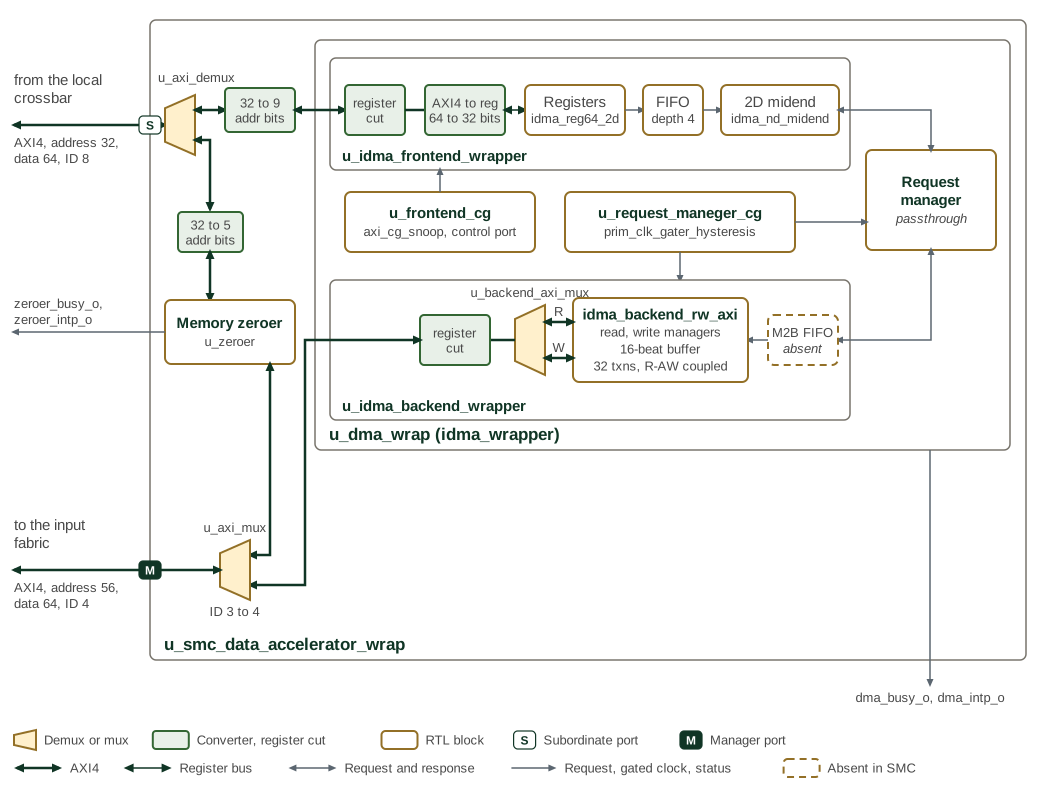
The DMA and the zeroer share smc_data_accelerator_wrap. Its control demux sends the
zeroer register window to the zeroer and every other address to the DMA, and each
control path narrows the address to its own register window. Its master mux merges the
two master ports onto the port to the input fabric and adds one ID bit to tell their
responses apart. In the figure, thick lines are AXI4, thin dark lines are the register
bus, and grey lines are iDMA requests and responses, gated clocks and status outputs.
The dashed box is the manager-to-backend FIFO, which is absent because SMC sets
M2B_FIFO_DEPTH to 0. With one control interface and one master interface, the
request manager is a passthrough, so the arbitration described under
[smc-dma-request-arbitration] is not instantiated.
The generic request manager can arbitrate multiple control/master interfaces with round-robin selection, per-master origin tracking and buffered response routing. In the instantiated one-control/one-master SMC configuration it is a passthrough; these generic arbitration features add no extra SMC streams.
| Parameter | SMC value | Meaning |
|---|---|---|
|
1 each |
One shared configuration, one functional stream and one DMA master. |
|
32 |
Backend in-flight AXI limit, from |
|
4 |
Request FIFO between frontend and 2D midend. |
|
0 |
Midend-to-backend FIFO bypassed. |
|
16 |
Backend realignment buffer depth in beats; the generic wrapper default is 3. It is not a reorder-buffer entry count. |
|
1 |
Backend read/write address coupling enabled. |
|
0 each |
Interface cuts retained. |
|
6 |
Width of the runtime clock-gating hysteresis input. |
The parameters of idma_wrapper are listed in idma_wrapper.
The frontend has a bus-aware clock gate; the request manager and backend use a
separate activity/hysteresis gate. cg_enable_i=0 keeps them awake, and test
mode overrides gating. Clock gating does not abort transfers or isolate the bus.
2. Transfer Configuration
2.1. Stream and Register Ownership
The generated map contains NEXT_ID, STATUS and DONE banks for 16 streams,
but only bank 0 is functional in SMC. Reads of NEXT_ID_1..15 complete with zero
and launch nothing; their STATUS and DONE registers also read zero. A read of
NEXT_ID_0 is a command, not a status read: any read whose bytes include
NEXT_ID_0, such as a 64-bit read at 0x48, launches a transfer; a 32-bit read
of the unused word at 0x4C does not.
Source, destination, length, strides, repetitions and CONFIG are registers
shared by all software contexts, with no configuration-lock register. The 64-bit
fields use low/high 32-bit register halves, which the register path does not
update atomically.
| Field | CSR storage | Effective width | Use |
|---|---|---|---|
|
64 bits each |
56 bits each |
Byte addresses. |
|
64 bits |
56 bits |
Bytes per linear copy or per 2D row. Zero-length transfers are rejected. |
|
64 bits each |
56 bits each |
Address increment between consecutive row starts; source and destination increments are independent. |
|
64 bits |
32 bits |
Number of rows, including the first. |
The frontend casts register values to these effective widths: upper bits are discarded, not validated as an out-of-range access. Program unused upper bits as zero and ensure all row addresses and lengths fit the permitted address range. Address stepping uses the effective address width.
2.2. Linear and Two-Dimensional Copies
A linear copy is one repetition with CONFIG.ENABLED_ND set; a 2D copy adds
source/destination strides and a repetition count. Strides can gather or
scatter evenly spaced rows; there is no linked-list walker.
Clearing CONFIG.ENABLED_ND forces the midend repetition count to zero. A zero-repetition command produces an internal
midend error response without data movement; that response still retires a
transfer ID. The control aperture does not expose the error payload, so a
retired ID alone is not proof that valid data was copied.
The names above follow the published register map. The RTL frontend calls the
configuration conf, the ND-enable field enable_nd, and the repetition pair
reps_2_low/high; these refer to the same fields.
The frontend requests incrementing AXI bursts and sets the cache attribute to
modifiable. CONFIG supplies decoupling, maximum burst-length and length-reduction
options; the CONFIG register description gives each field’s effect. The backend
handles alignment and burst splitting; these mechanisms do not grant permission
to access a filtered or otherwise invalid address.
3. Submission and Completion
The DMA Engine section of the Programmer’s Guide gives the submission and completion sequence.
| Indication | Meaning |
|---|---|
|
Eight copies of frontend request readiness: |
|
Bit 8 is the midend activity indication; bit 9 is zero. |
|
Most recently retired transfer ID. No byte-progress or classified software error-status register is provided. |
DMA interrupt |
One-cycle pulse on a falling edge of combined frontend/backend busy, routed to raw CPU vector bit 322 (PLIC ID 323). No local enable, mask or pending register; this is not one interrupt per submitted descriptor. |
Frontend readiness and a zero STATUS value do not indicate completion.
The transfer-ID generator resets NEXT_ID to 2 and DONE to 1 and skips zero
on wrap. PLIC gateway behavior does not turn successive busy-falling pulses
into a counted queue.
4. Memory Map and Register Reference
4.1. Memory Map
The register map below covers all 16 stream banks because the
register file is generated at the maximum stream count. With
NUM_CTRL_STREAMS = 1, only the _0 bank of NEXT_ID, STATUS, and
DONE has any effect; see Section 2.1.
|
4.2. Detailed Register Map
iDMA Controller Address Map
Source, destination, length, and control registers for the iDMA data-mover engine.
Register List:
Register Details:
CONFIG
| Bits | Field | Access | Reset | Description |
|---|---|---|---|---|
| 31:11 | Reserved | - | - | Reserved |
| 10 | ENABLED_ND | RW | 0x0 | Repetition enable. 1: the copy is performed NUM_REPETITIONS times, with SRC_STRIDE and DST_STRIDE added to the addresses between rows; set it for every transfer, including a linear copy with NUM_REPETITIONS = 1. 0: the repetition count is forced to zero, so the command completes with an error response, moves no data, and still retires its transfer ID. |
| 9:7 | DST_MAX_LLEN | RW | 0x0 | Base-2 logarithm of the maximum write burst length in 64-bit beats, applied when DST_REDUCE_LEN is 1. A write burst does not cross a boundary aligned to 2^(DST_MAX_LLEN+3) bytes; 0 gives single-beat bursts. Ignored when DST_REDUCE_LEN is 0. |
| 6:4 | SRC_MAX_LLEN | RW | 0x0 | Base-2 logarithm of the maximum read burst length in 64-bit beats, applied when SRC_REDUCE_LEN is 1. A read burst does not cross a boundary aligned to 2^(SRC_MAX_LLEN+3) bytes; 0 gives single-beat bursts. Ignored when SRC_REDUCE_LEN is 0. |
| 3 | DST_REDUCE_LEN | RW | 0x0 | Destination burst-length reduction. 1: write bursts are limited by DST_MAX_LLEN. 0: a write burst is at most 256 beats and does not cross a 2 KiB-aligned boundary. |
| 2 | SRC_REDUCE_LEN | RW | 0x0 | Source burst-length reduction. 1: read bursts are limited by SRC_MAX_LLEN. 0: a read burst is at most 256 beats and does not cross a 2 KiB-aligned boundary. |
| 1 | DECOUPLE_RW | RW | 0x0 | Read/write decoupling. 0: read and write bursts are formed in lockstep, one write burst per read burst. 1: read and write bursts are formed and issued independently; this mode can deadlock. |
| 0 | DECOUPLE_AW | RW | 0x0 | Write-address decoupling. 0: the write address of each burst is held until the first data beat of that burst is ready to be written. 1: write addresses are issued without waiting for write data. |
STATUS_0
| Bits | Field | Access | Reset | Description |
|---|---|---|---|---|
| 31:10 | Reserved | - | - | Reserved |
| 9:0 | BUSY | R | 0x0 | Status for the active stream: bits [7:0] each indicate readiness to accept another command, bit 8 indicates midend activity, and bit 9 is zero. These bits do not report backend busy or prove transfer completion; use DONE for completed transfer IDs. Unused streams read zero. |
STATUS_1
| Bits | Field | Access | Reset | Description |
|---|---|---|---|---|
| 31:10 | Reserved | - | - | Reserved |
| 9:0 | BUSY | R | 0x0 | Status for the active stream: bits [7:0] each indicate readiness to accept another command, bit 8 indicates midend activity, and bit 9 is zero. These bits do not report backend busy or prove transfer completion; use DONE for completed transfer IDs. Unused streams read zero. |
STATUS_2
| Bits | Field | Access | Reset | Description |
|---|---|---|---|---|
| 31:10 | Reserved | - | - | Reserved |
| 9:0 | BUSY | R | 0x0 | Status for the active stream: bits [7:0] each indicate readiness to accept another command, bit 8 indicates midend activity, and bit 9 is zero. These bits do not report backend busy or prove transfer completion; use DONE for completed transfer IDs. Unused streams read zero. |
STATUS_3
| Bits | Field | Access | Reset | Description |
|---|---|---|---|---|
| 31:10 | Reserved | - | - | Reserved |
| 9:0 | BUSY | R | 0x0 | Status for the active stream: bits [7:0] each indicate readiness to accept another command, bit 8 indicates midend activity, and bit 9 is zero. These bits do not report backend busy or prove transfer completion; use DONE for completed transfer IDs. Unused streams read zero. |
STATUS_4
| Bits | Field | Access | Reset | Description |
|---|---|---|---|---|
| 31:10 | Reserved | - | - | Reserved |
| 9:0 | BUSY | R | 0x0 | Status for the active stream: bits [7:0] each indicate readiness to accept another command, bit 8 indicates midend activity, and bit 9 is zero. These bits do not report backend busy or prove transfer completion; use DONE for completed transfer IDs. Unused streams read zero. |
STATUS_5
| Bits | Field | Access | Reset | Description |
|---|---|---|---|---|
| 31:10 | Reserved | - | - | Reserved |
| 9:0 | BUSY | R | 0x0 | Status for the active stream: bits [7:0] each indicate readiness to accept another command, bit 8 indicates midend activity, and bit 9 is zero. These bits do not report backend busy or prove transfer completion; use DONE for completed transfer IDs. Unused streams read zero. |
STATUS_6
| Bits | Field | Access | Reset | Description |
|---|---|---|---|---|
| 31:10 | Reserved | - | - | Reserved |
| 9:0 | BUSY | R | 0x0 | Status for the active stream: bits [7:0] each indicate readiness to accept another command, bit 8 indicates midend activity, and bit 9 is zero. These bits do not report backend busy or prove transfer completion; use DONE for completed transfer IDs. Unused streams read zero. |
STATUS_7
| Bits | Field | Access | Reset | Description |
|---|---|---|---|---|
| 31:10 | Reserved | - | - | Reserved |
| 9:0 | BUSY | R | 0x0 | Status for the active stream: bits [7:0] each indicate readiness to accept another command, bit 8 indicates midend activity, and bit 9 is zero. These bits do not report backend busy or prove transfer completion; use DONE for completed transfer IDs. Unused streams read zero. |
STATUS_8
| Bits | Field | Access | Reset | Description |
|---|---|---|---|---|
| 31:10 | Reserved | - | - | Reserved |
| 9:0 | BUSY | R | 0x0 | Status for the active stream: bits [7:0] each indicate readiness to accept another command, bit 8 indicates midend activity, and bit 9 is zero. These bits do not report backend busy or prove transfer completion; use DONE for completed transfer IDs. Unused streams read zero. |
STATUS_9
| Bits | Field | Access | Reset | Description |
|---|---|---|---|---|
| 31:10 | Reserved | - | - | Reserved |
| 9:0 | BUSY | R | 0x0 | Status for the active stream: bits [7:0] each indicate readiness to accept another command, bit 8 indicates midend activity, and bit 9 is zero. These bits do not report backend busy or prove transfer completion; use DONE for completed transfer IDs. Unused streams read zero. |
STATUS_10
| Bits | Field | Access | Reset | Description |
|---|---|---|---|---|
| 31:10 | Reserved | - | - | Reserved |
| 9:0 | BUSY | R | 0x0 | Status for the active stream: bits [7:0] each indicate readiness to accept another command, bit 8 indicates midend activity, and bit 9 is zero. These bits do not report backend busy or prove transfer completion; use DONE for completed transfer IDs. Unused streams read zero. |
STATUS_11
| Bits | Field | Access | Reset | Description |
|---|---|---|---|---|
| 31:10 | Reserved | - | - | Reserved |
| 9:0 | BUSY | R | 0x0 | Status for the active stream: bits [7:0] each indicate readiness to accept another command, bit 8 indicates midend activity, and bit 9 is zero. These bits do not report backend busy or prove transfer completion; use DONE for completed transfer IDs. Unused streams read zero. |
STATUS_12
| Bits | Field | Access | Reset | Description |
|---|---|---|---|---|
| 31:10 | Reserved | - | - | Reserved |
| 9:0 | BUSY | R | 0x0 | Status for the active stream: bits [7:0] each indicate readiness to accept another command, bit 8 indicates midend activity, and bit 9 is zero. These bits do not report backend busy or prove transfer completion; use DONE for completed transfer IDs. Unused streams read zero. |
STATUS_13
| Bits | Field | Access | Reset | Description |
|---|---|---|---|---|
| 31:10 | Reserved | - | - | Reserved |
| 9:0 | BUSY | R | 0x0 | Status for the active stream: bits [7:0] each indicate readiness to accept another command, bit 8 indicates midend activity, and bit 9 is zero. These bits do not report backend busy or prove transfer completion; use DONE for completed transfer IDs. Unused streams read zero. |
STATUS_14
| Bits | Field | Access | Reset | Description |
|---|---|---|---|---|
| 31:10 | Reserved | - | - | Reserved |
| 9:0 | BUSY | R | 0x0 | Status for the active stream: bits [7:0] each indicate readiness to accept another command, bit 8 indicates midend activity, and bit 9 is zero. These bits do not report backend busy or prove transfer completion; use DONE for completed transfer IDs. Unused streams read zero. |
STATUS_15
| Bits | Field | Access | Reset | Description |
|---|---|---|---|---|
| 31:10 | Reserved | - | - | Reserved |
| 9:0 | BUSY | R | 0x0 | Status for the active stream: bits [7:0] each indicate readiness to accept another command, bit 8 indicates midend activity, and bit 9 is zero. These bits do not report backend busy or prove transfer completion; use DONE for completed transfer IDs. Unused streams read zero. |
NEXT_ID_0
| Bits | Field | Access | Reset | Description |
|---|---|---|---|---|
| 31:0 | DATA | R | 0x0 | Reading this register starts the DMA transfer. Returns an ID value for the cumulative number of transfers. Returns 0 if command was not set up correctly |
NEXT_ID_1
| Bits | Field | Access | Reset | Description |
|---|---|---|---|---|
| 31:0 | DATA | R | 0x0 | Reading this register starts the DMA transfer. Returns an ID value for the cumulative number of transfers. Returns 0 if command was not set up correctly |
NEXT_ID_2
| Bits | Field | Access | Reset | Description |
|---|---|---|---|---|
| 31:0 | DATA | R | 0x0 | Reading this register starts the DMA transfer. Returns an ID value for the cumulative number of transfers. Returns 0 if command was not set up correctly |
NEXT_ID_3
| Bits | Field | Access | Reset | Description |
|---|---|---|---|---|
| 31:0 | DATA | R | 0x0 | Reading this register starts the DMA transfer. Returns an ID value for the cumulative number of transfers. Returns 0 if command was not set up correctly |
NEXT_ID_4
| Bits | Field | Access | Reset | Description |
|---|---|---|---|---|
| 31:0 | DATA | R | 0x0 | Reading this register starts the DMA transfer. Returns an ID value for the cumulative number of transfers. Returns 0 if command was not set up correctly |
NEXT_ID_5
| Bits | Field | Access | Reset | Description |
|---|---|---|---|---|
| 31:0 | DATA | R | 0x0 | Reading this register starts the DMA transfer. Returns an ID value for the cumulative number of transfers. Returns 0 if command was not set up correctly |
NEXT_ID_6
| Bits | Field | Access | Reset | Description |
|---|---|---|---|---|
| 31:0 | DATA | R | 0x0 | Reading this register starts the DMA transfer. Returns an ID value for the cumulative number of transfers. Returns 0 if command was not set up correctly |
NEXT_ID_7
| Bits | Field | Access | Reset | Description |
|---|---|---|---|---|
| 31:0 | DATA | R | 0x0 | Reading this register starts the DMA transfer. Returns an ID value for the cumulative number of transfers. Returns 0 if command was not set up correctly |
NEXT_ID_8
| Bits | Field | Access | Reset | Description |
|---|---|---|---|---|
| 31:0 | DATA | R | 0x0 | Reading this register starts the DMA transfer. Returns an ID value for the cumulative number of transfers. Returns 0 if command was not set up correctly |
NEXT_ID_9
| Bits | Field | Access | Reset | Description |
|---|---|---|---|---|
| 31:0 | DATA | R | 0x0 | Reading this register starts the DMA transfer. Returns an ID value for the cumulative number of transfers. Returns 0 if command was not set up correctly |
NEXT_ID_10
| Bits | Field | Access | Reset | Description |
|---|---|---|---|---|
| 31:0 | DATA | R | 0x0 | Reading this register starts the DMA transfer. Returns an ID value for the cumulative number of transfers. Returns 0 if command was not set up correctly |
NEXT_ID_11
| Bits | Field | Access | Reset | Description |
|---|---|---|---|---|
| 31:0 | DATA | R | 0x0 | Reading this register starts the DMA transfer. Returns an ID value for the cumulative number of transfers. Returns 0 if command was not set up correctly |
NEXT_ID_12
| Bits | Field | Access | Reset | Description |
|---|---|---|---|---|
| 31:0 | DATA | R | 0x0 | Reading this register starts the DMA transfer. Returns an ID value for the cumulative number of transfers. Returns 0 if command was not set up correctly |
NEXT_ID_13
| Bits | Field | Access | Reset | Description |
|---|---|---|---|---|
| 31:0 | DATA | R | 0x0 | Reading this register starts the DMA transfer. Returns an ID value for the cumulative number of transfers. Returns 0 if command was not set up correctly |
NEXT_ID_14
| Bits | Field | Access | Reset | Description |
|---|---|---|---|---|
| 31:0 | DATA | R | 0x0 | Reading this register starts the DMA transfer. Returns an ID value for the cumulative number of transfers. Returns 0 if command was not set up correctly |
NEXT_ID_15
| Bits | Field | Access | Reset | Description |
|---|---|---|---|---|
| 31:0 | DATA | R | 0x0 | Reading this register starts the DMA transfer. Returns an ID value for the cumulative number of transfers. Returns 0 if command was not set up correctly |
DONE_0
| Bits | Field | Access | Reset | Description |
|---|---|---|---|---|
| 31:0 | DATA | R | 0x0 | Holds the cumulative number of completed transfers. Only accumulates when response is seen |
DONE_1
| Bits | Field | Access | Reset | Description |
|---|---|---|---|---|
| 31:0 | DATA | R | 0x0 | Holds the cumulative number of completed transfers. Only accumulates when response is seen |
DONE_2
| Bits | Field | Access | Reset | Description |
|---|---|---|---|---|
| 31:0 | DATA | R | 0x0 | Holds the cumulative number of completed transfers. Only accumulates when response is seen |
DONE_3
| Bits | Field | Access | Reset | Description |
|---|---|---|---|---|
| 31:0 | DATA | R | 0x0 | Holds the cumulative number of completed transfers. Only accumulates when response is seen |
DONE_4
| Bits | Field | Access | Reset | Description |
|---|---|---|---|---|
| 31:0 | DATA | R | 0x0 | Holds the cumulative number of completed transfers. Only accumulates when response is seen |
DONE_5
| Bits | Field | Access | Reset | Description |
|---|---|---|---|---|
| 31:0 | DATA | R | 0x0 | Holds the cumulative number of completed transfers. Only accumulates when response is seen |
DONE_6
| Bits | Field | Access | Reset | Description |
|---|---|---|---|---|
| 31:0 | DATA | R | 0x0 | Holds the cumulative number of completed transfers. Only accumulates when response is seen |
DONE_7
| Bits | Field | Access | Reset | Description |
|---|---|---|---|---|
| 31:0 | DATA | R | 0x0 | Holds the cumulative number of completed transfers. Only accumulates when response is seen |
DONE_8
| Bits | Field | Access | Reset | Description |
|---|---|---|---|---|
| 31:0 | DATA | R | 0x0 | Holds the cumulative number of completed transfers. Only accumulates when response is seen |
DONE_9
| Bits | Field | Access | Reset | Description |
|---|---|---|---|---|
| 31:0 | DATA | R | 0x0 | Holds the cumulative number of completed transfers. Only accumulates when response is seen |
DONE_10
| Bits | Field | Access | Reset | Description |
|---|---|---|---|---|
| 31:0 | DATA | R | 0x0 | Holds the cumulative number of completed transfers. Only accumulates when response is seen |
DONE_11
| Bits | Field | Access | Reset | Description |
|---|---|---|---|---|
| 31:0 | DATA | R | 0x0 | Holds the cumulative number of completed transfers. Only accumulates when response is seen |
DONE_12
| Bits | Field | Access | Reset | Description |
|---|---|---|---|---|
| 31:0 | DATA | R | 0x0 | Holds the cumulative number of completed transfers. Only accumulates when response is seen |
DONE_13
| Bits | Field | Access | Reset | Description |
|---|---|---|---|---|
| 31:0 | DATA | R | 0x0 | Holds the cumulative number of completed transfers. Only accumulates when response is seen |
DONE_14
| Bits | Field | Access | Reset | Description |
|---|---|---|---|---|
| 31:0 | DATA | R | 0x0 | Holds the cumulative number of completed transfers. Only accumulates when response is seen |
DONE_15
| Bits | Field | Access | Reset | Description |
|---|---|---|---|---|
| 31:0 | DATA | R | 0x0 | Holds the cumulative number of completed transfers. Only accumulates when response is seen |
DST_ADDRESS_LO
| Bits | Field | Access | Reset | Description |
|---|---|---|---|---|
| 31:0 | DATA | RW | 0x0 | Destination address for DMA to write to, lower 32 bits |
DST_ADDRESS_HI
| Bits | Field | Access | Reset | Description |
|---|---|---|---|---|
| 31:0 | DATA | RW | 0x0 | Destination address for DMA to write to, upper 32 bits. Bits [31:24] (combined address bits [63:56]) are discarded, not checked; program them as zero. |
SRC_ADDRESS_LO
| Bits | Field | Access | Reset | Description |
|---|---|---|---|---|
| 31:0 | DATA | RW | 0x0 | Source address for DMA to read from, lower 32 bits. |
SRC_ADDRESS_HI
| Bits | Field | Access | Reset | Description |
|---|---|---|---|---|
| 31:0 | DATA | RW | 0x0 | Source address for DMA to read from, upper 32 bits. Bits [31:24] (combined address bits [63:56]) are discarded, not checked; program them as zero. |
LENGTH_LO
| Bits | Field | Access | Reset | Description |
|---|---|---|---|---|
| 31:0 | DATA | RW | 0x0 | Number of bytes to move, lower 32 bits. |
LENGTH_HI
| Bits | Field | Access | Reset | Description |
|---|---|---|---|---|
| 31:0 | DATA | RW | 0x0 | Number of bytes to move, upper 32 bits. Bits [31:24] (combined length bits [63:56]) are discarded, not checked; program them as zero. |
DST_STRIDE_LO
| Bits | Field | Access | Reset | Description |
|---|---|---|---|---|
| 31:0 | DATA | RW | 0x0 | Stride amount on destination address side, lower 32 bits |
DST_STRIDE_HI
| Bits | Field | Access | Reset | Description |
|---|---|---|---|---|
| 31:0 | DATA | RW | 0x0 | Stride amount on destination address side, upper 32 bits. Bits [31:24] (combined stride bits [63:56]) are discarded, not checked; program them as zero. |
SRC_STRIDE_LO
| Bits | Field | Access | Reset | Description |
|---|---|---|---|---|
| 31:0 | DATA | RW | 0x0 | Stride amount on source address side, lower 32 bits |
SRC_STRIDE_HI
| Bits | Field | Access | Reset | Description |
|---|---|---|---|---|
| 31:0 | DATA | RW | 0x0 | Stride amount on source address side, upper 32 bits. Bits [31:24] (combined stride bits [63:56]) are discarded, not checked; program them as zero. |
NUM_REPETITIONS_LO
| Bits | Field | Access | Reset | Description |
|---|---|---|---|---|
| 31:0 | DATA | RW | 0x0 | Number of rows to copy, including the first, lower 32 bits. SRC_STRIDE and DST_STRIDE are added to the addresses between rows. Takes effect only when CONFIG.ENABLED_ND is 1. |
NUM_REPETITIONS_HI
| Bits | Field | Access | Reset | Description |
|---|---|---|---|---|
| 31:0 | DATA | RW | 0x0 | Number of rows to copy, upper 32 bits. The DMA uses only the low 32 bits of the row count, so this register is discarded, not checked; program it as zero. |