Cross-Trigger Port
The Cross Trigger Port (CTP) is the pad-facing signalling module for cross-trigger communication per the Open Chiplet Cross Triggering (OCCT) specification. Each CTP connects the chiplet core logic to four I/O pads and handles the timing and handshaking required for both wire-OR and point-to-point signalling schemes.
1. Overview
Each CTP connects to four I/O pads:
-
CT_Req_out — cross-trigger request output.
-
CT_Ack_in — acknowledge input (point-to-point only).
-
CT_Req_in — cross-trigger request input (point-to-point only).
-
CT_Ack_out — acknowledge output (point-to-point only).
Two inter-chiplet signalling schemes are supported:
-
Wire-OR — supports a wide range of existing chiplet implementations and is resource efficient. Uses pulse stretching to ensure reliable detection across chiplet boundary delays.
-
Point-to-point — faster, more reliable, and simpler to configure. Uses four-phase handshaking with CDC synchronisers at the die boundary.
2. Configuration
The CTP has no build-time parameters. All operational settings are programmed at runtime through the AXI-Lite CSR interface:
Table 1 summarises the runtime controls exposed through the CTP CSR interface.
| Register | Description |
|---|---|
|
Select wire-OR (0) or point-to-point (1) signalling. |
|
16-bit pulse stretch multiplier for wire-OR mode. |
|
Signal polarity inversion for GPIO adaptation. |
|
Handshake state machine reset. |
See the CTN Memory Map for the full CTP register layout and field descriptions. The CTN decodes the AXI-Lite CSR window and presents each CTP’s registers at a 16-byte stride starting at offset 0x0200.
MODE and INVERT are static configuration, set once per boot in a single
write before any CTM route selects or targets the port. The Programmer’s Guide
gives the
cross-trigger programming sequence
with reconfiguration and deadlock recovery.
3. Architecture
The Cross Trigger Port architecture separates the register interface from core
logic to enable reuse. The full cross_trigger_port module includes CSRs for
runtime configuration, while the cross_trigger_port_core module provides the
core functionality without registers, allowing instantiation for internal
cross-trigger connections without AXI-Lite overhead.
Figure 1 shows the Cross Trigger Port logic and its pad interfaces.
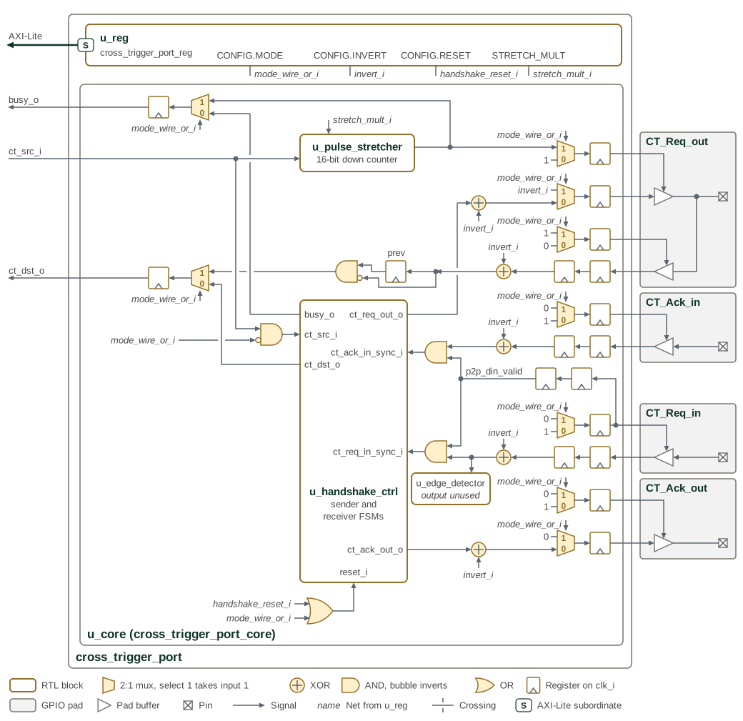
The figure is read from the core side on the left to the four GPIO pads on the
right. Every 2:1 mux is selected by mode_wire_or_i, and the numbers inside
it mark which input each select value takes. Input 1, drawn upper, passes in
wire-OR mode, when mode_wire_or_i is high because CONFIG.MODE is 0; input 0,
drawn lower, passes in point-to-point mode. Italic names are nets driven by
u_reg from the named CSR fields. Every pad control and both core-side outputs, ct_dst_o and busy_o,
leave the port through a register on clk_i. Each pad input passes through two
synchroniser registers and an XOR with invert_i and, on the handshake inputs, an
AND with p2p_din_valid before any logic uses it. The
STATUS read-back from the core to u_reg is not drawn.
3.1. Submodule Hierarchy
The CTP core instantiates four specialized submodules for different aspects of cross-trigger operation:
Table 2 identifies the submodules that implement synchronization and cross-trigger operation.
| Module | Purpose |
|---|---|
|
Implements 2-FF synchronizers for asynchronous GPIO inputs (ct_req_out_din, ct_req_in_din, ct_ack_in_din) from remote chiplets |
|
Extends source pulse duration for Wire-OR mode transmission, with configurable stretch multiplier (0-65535 cycles) |
|
Detects positive edges on the synchronized ct_req_in signal; its output is not connected, because the receiver state machine works on the ct_req_in level |
|
Implements sender and receiver state machines for Point-to-Point mode four-phase handshaking protocol |
3.2. Wire-OR Mode
Wire-OR mode is a 1-wire cross trigger signaling scheme compatible with many existing cross triggering implementations. This scheme is very resource efficient, as it only requires a single pin per chiplet connected to the network. However, the performance of the network decreases as the number of connected chiplets increase. Also, the duration of the cross trigger pulse must be pre-arranged across all connected chiplets.
3.2.1. Pulse Stretcher Operation
The pulse stretcher extends single-cycle core-side pulses to multi-cycle GPIO
assertions lasting stretch_mult + 1 clock cycles. The module implements a
16-bit countdown counter that loads the stretch multiplier value when a new
pulse arrives and decrements to zero. If a new pulse arrives before the counter
reaches zero, the counter restarts from the stretch multiplier value, ensuring
that rapid successive pulses merge into an extended assertion.
The output stretched_pulse remains asserted as long as the counter is
non-zero. This stretched pulse drives the output enable control for the
open-drain CT_Req_out GPIO pad, effectively pulling the shared wire low for the
configured duration.
Each chiplet has an open-drain I/O connected to a single shared wire. Any connected chiplet may pull this signal low to assert a cross trigger. Depending on the electrical requirements, one or more internal pad pull-ups or external keepers ensure the cross trigger request signal remains high when no cross trigger is asserted. To ensure no connected chiplet misses a cross trigger pulse, all chiplets transmitting a trigger pulse must stretch the pulse a mutually agreed upon length of time.
Note that in wire-OR mode the CT_Req_out signal is connected to an open-drain configured I/O pad. For I/O pads that do have explicit open-drain control, the request data signal should connect to the output-enable control pin of the I/O pad, and the output data signal of the I/O pin should be driven statically low.
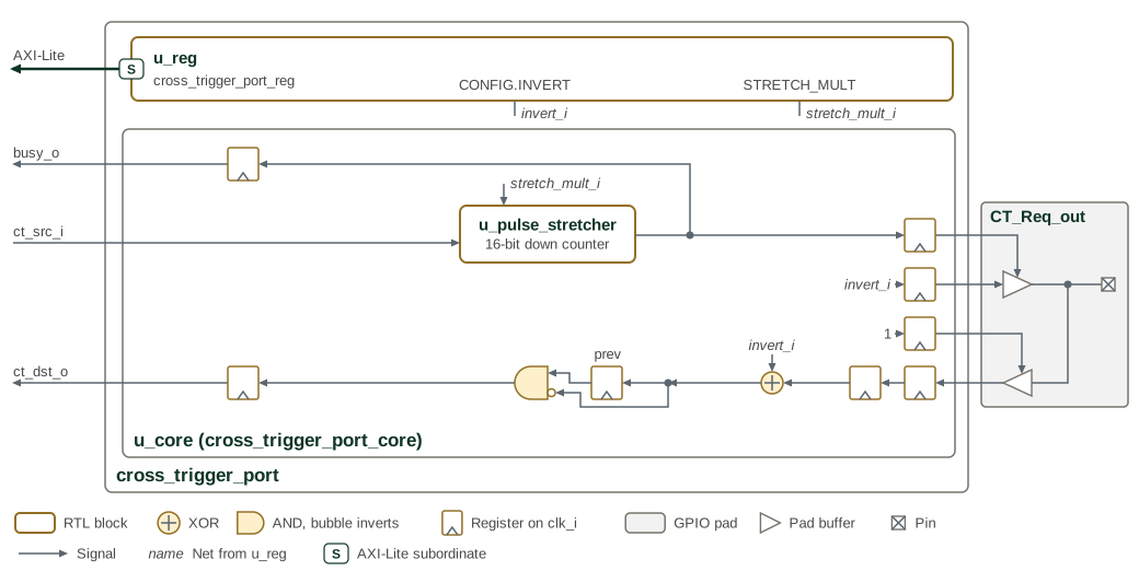
Figure 2 shows the open-drain request path and pulse-stretching
logic used in wire-OR mode. It is Figure 1 with every mux
resolved to its wire-OR input. The CT_Req_out pad drives the constant
invert_i, so its output enable, the stretched pulse, decides when the pad pulls
the wire. The CTP receives a cross trigger on the falling edge of the
synchronised wire: the register marked prev holds the previous level and the
AND gate fires when the previous level is high and the current one low. The
CTP disables the buffers of the other three pads in this mode, so they are not
drawn.
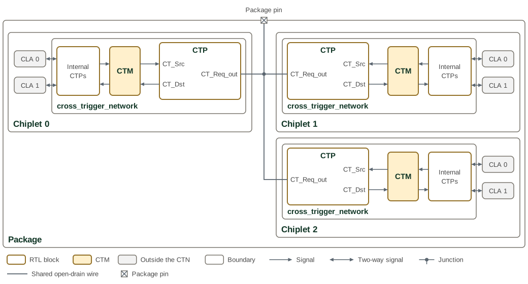
Any number of chiplets may have their CT_Req_out pads interconnected as shown in Figure 3. In each chiplet the CLAs reach the CTM through the internal CTPs of the Cross Trigger Network, and the CTM reaches the external CTP through its CT_Src and CT_Dst signals. The shared wire also reaches a package pin.
3.3. Point-to-Point Mode
Point-to-point mode utilizes a four-phase handshaking scheme to synchronize a cross trigger quickly and reliably between two chiplets without pulse stretching. While this scheme is simple and fast, it requires a dedicated CTP for each chiplet-to-chiplet interconnection, and each CTP requires four I/O pads for bi-directional communication, or two pads for unidirectional communication. All output pads are configured for push-pull operation.
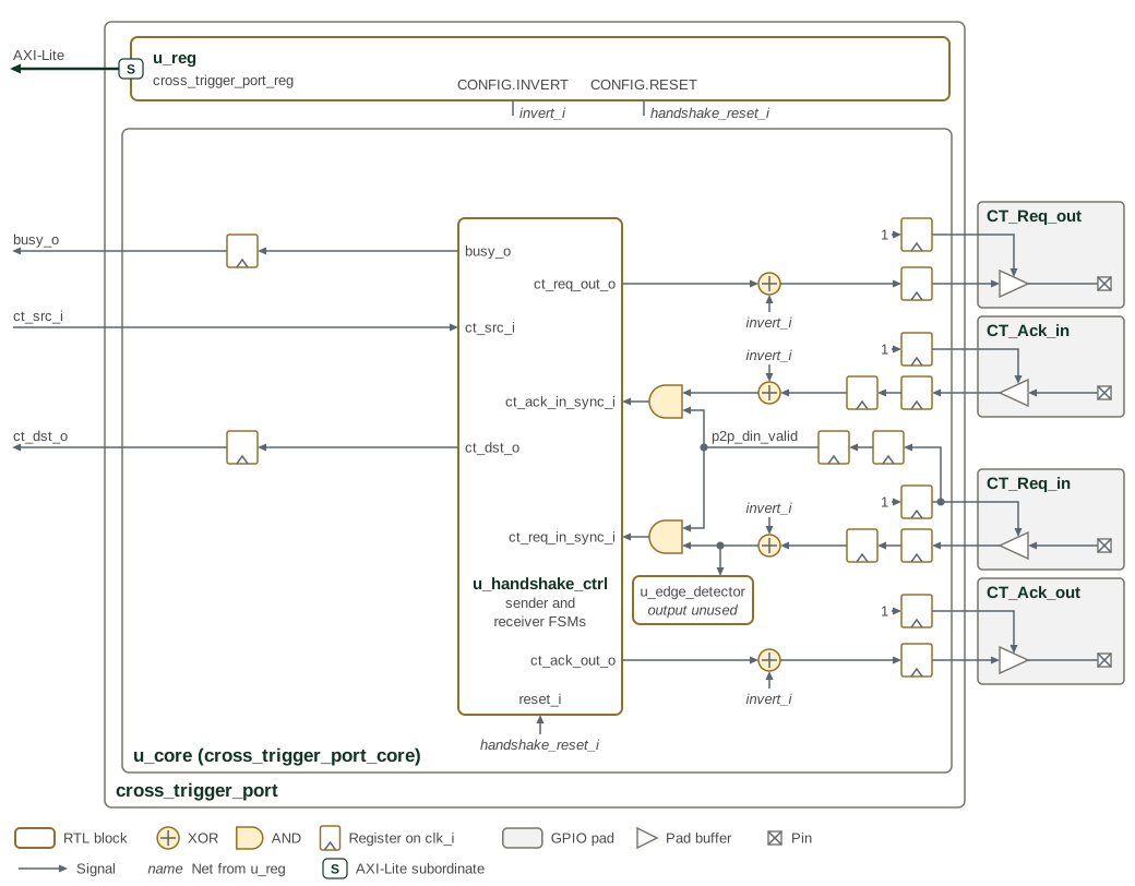
Figure 4 shows the request and acknowledge paths used for point-to-point handshaking. It is Figure 1 with every mux resolved to its point-to-point input. The output enables of CT_Req_out and CT_Ack_out and the input enables of CT_Ack_in and CT_Req_in are registered 1s. The input enable of the CT_Req_out pad is 0 in this mode, so only its output buffer is drawn, and the pulse stretcher and falling-edge detector are unused.
Any two chiplets may have their four cross trigger pads cross-coupled as shown in Figure 5. Each CTP lists its pads on the side that faces its partner, in the order that keeps every wire straight, so each request output meets a request input and each acknowledge output an acknowledge input.
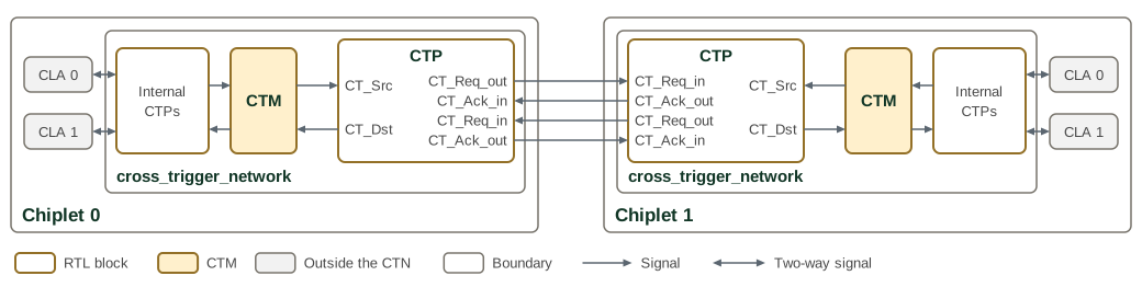
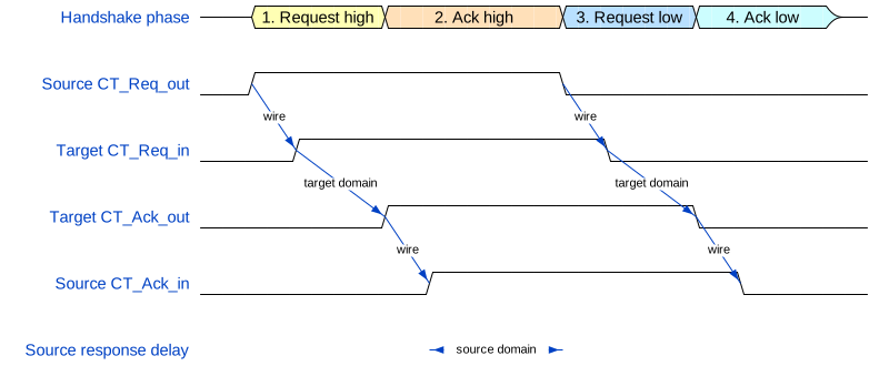
On the sender side, the receiver’s CT_Ack_out is connected to the sender’s CT_Ack_in pad. CT_Req_out asserts whenever CT_Src asserts. CT_Req_out will then remain asserted until CT_Ack_in asserts.
On the receiver side, the sender’s CT_Req_out is connected to the receiver’s CT_Req_in pad. On any positive edge of CT_Req_in, the receiver generates a pulse on CT_Dst and asserts CT_Ack_out. Deassertion proceeds in exactly the same sequence.
The timing of the request/acknowledge handshake is shown in Figure 6. The timing is illustrative, and the delays are not to scale:
3.3.1. Synchronization and CDC Handling
All GPIO input signals are asynchronous with respect to the CTP system clock and
require synchronization to prevent metastability. The ctp_synchronizer module
implements three independent 2-FF synchronizer chains using the
prim_flop_2sync primitive:
Table 3 identifies the incoming signals synchronized in each operating mode.
| Signal | Used In Mode | Synchronization Purpose |
|---|---|---|
|
Wire-OR |
Synchronizes open-drain wire state from remote chiplets before edge detection |
|
Point-to-Point |
Synchronizes request signal from remote sender before receiver FSM |
|
Point-to-Point |
Synchronizes acknowledge signal from remote receiver before sender FSM |
After synchronization, an optional inversion is applied if the INVERT
configuration bit is set. This allows adaptation to GPIO pads with different
polarity requirements. Edge detection and state machine processing occur only on
synchronized (and optionally inverted) signals, ensuring all CTP core logic
operates on glitch-free inputs.
3.3.2. Handshake State Machines
Point-to-point mode implements two independent state machines within the
ctp_handshake_ctrl module, enabling full-duplex cross-triggering. The sender
state machine controls outgoing cross-trigger requests, while the receiver state
machine handles incoming requests. Both state machines operate synchronously in
the system clock domain on synchronized GPIO inputs.
The state machines run only in point-to-point mode. While wire-OR mode is
selected, cross_trigger_port_core holds the sender in SENDER_IDLE with
ct_req_out=0 and blocks ct_src_i from reaching it. The CT_Req_in and
CT_Ack_in pad inputs are disabled in wire-OR mode, and after point-to-point
mode is selected their synchronizers hold the disabled pad level for two
cycles. The core presents both synchronized inputs to the state machines as
deasserted until the delayed input enable shows the synchronizers carry pad
data. Neither a trigger raised in wire-OR mode nor the level of a disabled pad
reaches the point-to-point pads when the mode changes.
Sender State Machine:
Table 4 lists the sender handshake states, transition conditions, and output actions.
| Current State | Condition | Next State | Output Actions |
|---|---|---|---|
SENDER_IDLE |
|
SENDER_REQ_ASSERTED |
Assert |
SENDER_REQ_ASSERTED |
|
SENDER_WAIT_ACK_DEASSERT |
De-assert |
SENDER_WAIT_ACK_DEASSERT |
|
SENDER_IDLE |
None (remain idle) |
Any state |
|
SENDER_IDLE |
Force |
Any state |
Wire-OR mode selected |
SENDER_IDLE |
Force |
Receiver State Machine:
Table 5 lists the receiver handshake states, transition conditions, and output actions.
| Current State | Condition | Next State | Output Actions |
|---|---|---|---|
RECEIVER_IDLE |
|
RECEIVER_ACK_ASSERTED |
Assert |
RECEIVER_ACK_ASSERTED |
|
RECEIVER_WAIT_REQ_DEASSERT |
De-assert |
RECEIVER_WAIT_REQ_DEASSERT |
|
RECEIVER_IDLE |
None |
RECEIVER_WAIT_REQ_DEASSERT |
|
Remain in state |
Continue waiting |
The ct_dst output pulse is generated for a single clock cycle when the
receiver state machine transitions from IDLE to ACK_ASSERTED. The busy signal
indicates an active cross-trigger transfer: it reflects either state machine
being outside its IDLE state. It is registered once in ctp_handshake_ctrl and
again in cross_trigger_port_core, so busy_o and STATUS.BUSY rise two
clk_i cycles after a state machine leaves IDLE and fall two clk_i cycles
after both state machines return to IDLE. Logic that samples busy_o within two
cycles of a trigger on ct_src_i, or of the end of a handshake, sees the
previous value.
4. Interface
4.1. Signal Interface
Packed control and bus types remain bundles at the cross_trigger_port module
boundary; their members are not separate scalar ports.
The parameters and ports of cross_trigger_port are listed in cross_trigger_port.
cross_trigger_port includes the CSR interface. The register-free cross_trigger_port_core instead takes mode_wire_or_i,
invert_i, handshake_reset_i, and stretch_mult_i as configuration inputs.
At that core interface, mode_wire_or_i = 1 selects wire-OR and 0 selects
point-to-point; the CSR MODE field is inverted before reaching it.
4.2. Dependencies
The CTP depends on the following components:
-
hw/common/ocah_prim- Primitive cells (synchronizers, pulse stretcher)