System Management Unit (SMU)
The System Management Unit (SMU) is the chiplet’s system-management subsystem. It integrates three functional blocks around a runtime-programmable AXI crossbar and presents a single boundary to the System Management Network (SMN).
1. Composition
-
Security Processor (SEP) — Root of Trust with a physically isolated RISC-V execution environment for secure boot, lifecycle control, device attestation and hardware-accelerated cryptography (OTBN PKA, AES, HMAC-SHA2, KMAC-SHA3, TRNG, DRBG, Key Manager).
-
System Management Controller (SMC) — Firmware-driven orchestration engine responsible for clock, voltage and reset management, platform bootstrapping, system initialisation, and power/thermal management. Built on a RISC-V micro-controller with DMA and memory-zeroer accelerators.
-
Debug and Test Ports (DTP) — Standardised debug and test access across heterogeneous, multi-vendor chiplet systems. Covers JTAG scan chains, JTAG2AXI debug bridges, cross-trigger network and synchronised clock control.
These three subsystems share a single primary clock domain (clk_smu_i) and
are released from reset by the SMC’s reset unit in a controlled sequence.
Platform-wide clock, power and reset behaviour is described in the
Clock Domains chapter.
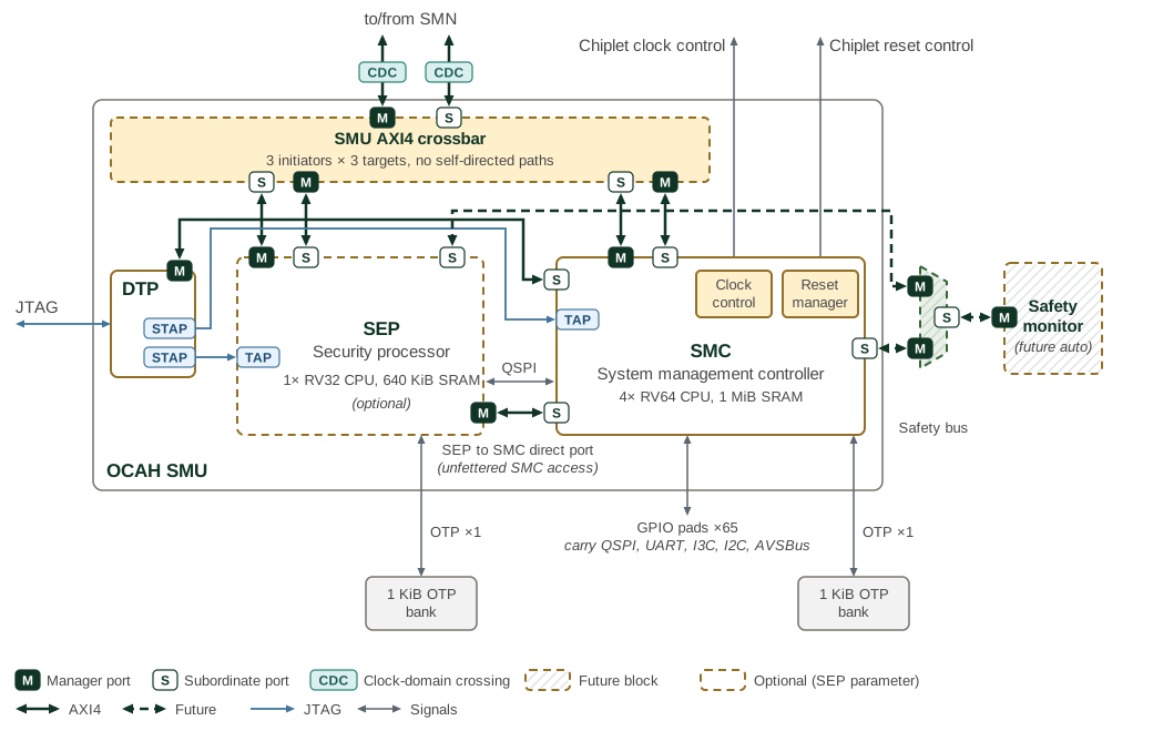
The SMU composition is shown in Figure 1.
Dashed outlines mark the blocks present only when CFG.SEP is 1: the SEP and
the AXI4 crossbar. Memory capacities in the diagram describe the
illustrated configuration. Hatched blocks are future: the safety bus and the
safety monitor, whose connections to the SEP and SMC are drawn dashed.
2. AXI Crossbar
Inside the SMU, the smu_axi_xbar module is the system-level arbitration
fabric between SEP, SMC, and the rest of the chiplet (reached through the
smu_axi_in / smu_axi_out boundary pair). It is a 3×3 AXI4 crossbar with
non-reflexive connectivity: each master can reach the other two subordinates
but never its own inbound port.
The SMU instantiates the crossbar only when CFG.SEP is 1. When CFG.SEP is
0, AXI ID-width converters connect the SMC system AXI ports to the
smu_axi_in / smu_axi_out pair: every SMC-initiated transaction leaves
through smu_axi_out, and every smu_axi_in transaction targets the SMC.
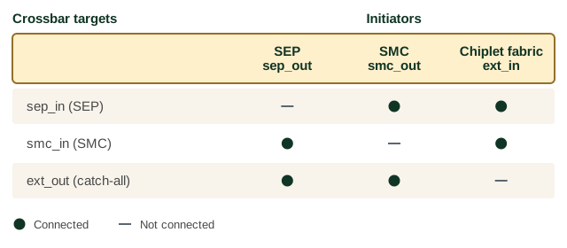
Table 1 lists the permitted initiator-to-subordinate paths and their purposes.
| Master (from) | Subordinate (to) | Purpose |
|---|---|---|
|
|
SEP-initiated transactions into SMC resources |
|
|
SEP-initiated transactions leaving the SMU |
|
|
SMC-initiated transactions into SEP resources |
|
|
SMC-initiated transactions leaving the SMU |
|
|
External transactions targeting SEP |
|
|
External transactions targeting SMC |
Routing decisions use a runtime address map with two programmable rules, the
SEP and SMC apertures. ext_out has no address rule; it is the default
subordinate for sep_out and smc_out requests that match neither aperture.
See
OCAH Memory Map
for the fixed-vs-programmable split and the reference envelope convention, and
see the SMU AXI Crossbar Address Map section in the Integrator Guide for
firmware programming order.
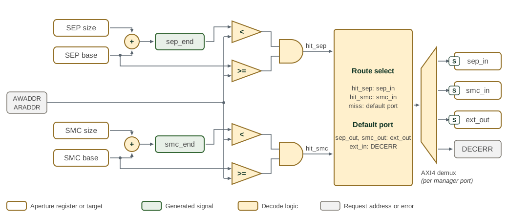
Figure 3 shows the independent SEP and SMC address
comparisons for each read or write request. Each aperture includes its base
address and excludes base + size; the addition uses 57 bits to preserve
carry from the 56-bit address, and the address is zero-extended to 57 bits for
the comparison. The SEP and SMC ranges must not overlap.
The decoded aperture and the connectivity in Figure 2 together determine where each request goes, as Table 2 shows.
| Initiator | SEP aperture | SMC aperture | Neither aperture |
|---|---|---|---|
|
|
|
|
|
|
|
|
|
|
|
|
-
A
sep_outorsmc_outrequest that matches neither aperture is forwarded toext_out. -
A
sep_outrequest that matches the SEP aperture, or ansmc_outrequest that matches the SMC aperture, returnsDECERR, because no initiator is connected to its own subsystem’s inbound port. -
An
ext_inrequest that matches neither aperture returnsDECERR, becauseext_inis not connected toext_out.
The crossbar generates each DECERR response itself; the request reaches no
subordinate.
3. Clocks and Resets
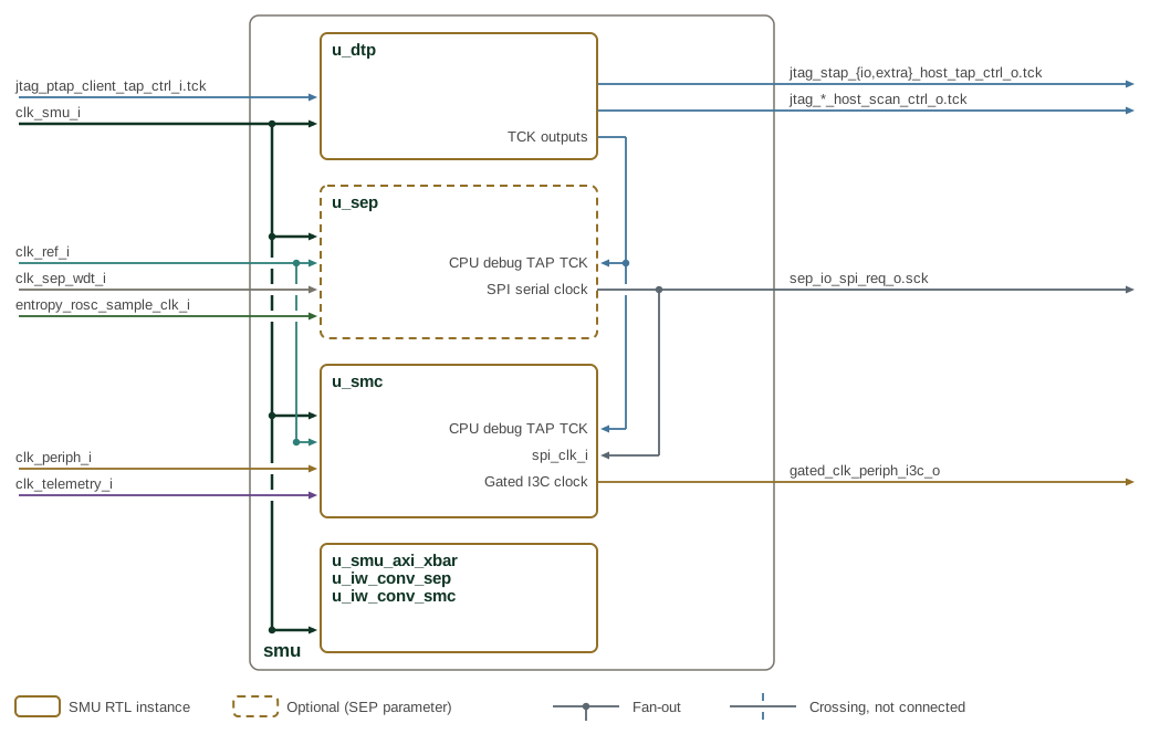
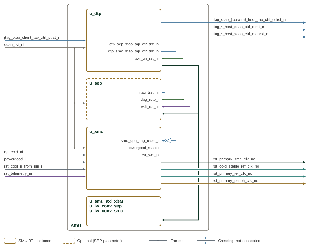
Figure 4 and Figure 5 show the clock and
reset distribution from the SMU boundary to DTP, SEP, SMC, and the shared
AXI infrastructure. Boundary inputs enter on the left and boundary outputs
leave on the right; nets generated inside the SMU run in the channel to the
right of the instances. A dot marks fan-out, and a gap in a line marks a
crossing without a connection. Labels at an instance’s right edge name the
net it drives or the port that receives a generated net. Instance names match
the SMU RTL hierarchy, and paths to the SEP exist only when CFG.SEP
is 1.
Active-low resets use the _ni, _no or trst_n suffixes; the SMC CPU JTAG
reset is active-high, so dtp_smc_stap_tap_ctrl.trst_n passes through an
inverter. Figure 5 shows reset distribution within the SMU,
not the reset logic inside each subsystem.
4. Lifecycle and Feature Control
SEP lifecycle state and feature controls constrain the debug paths in DTP and the management functions in SMC, as shown in Figure 6.
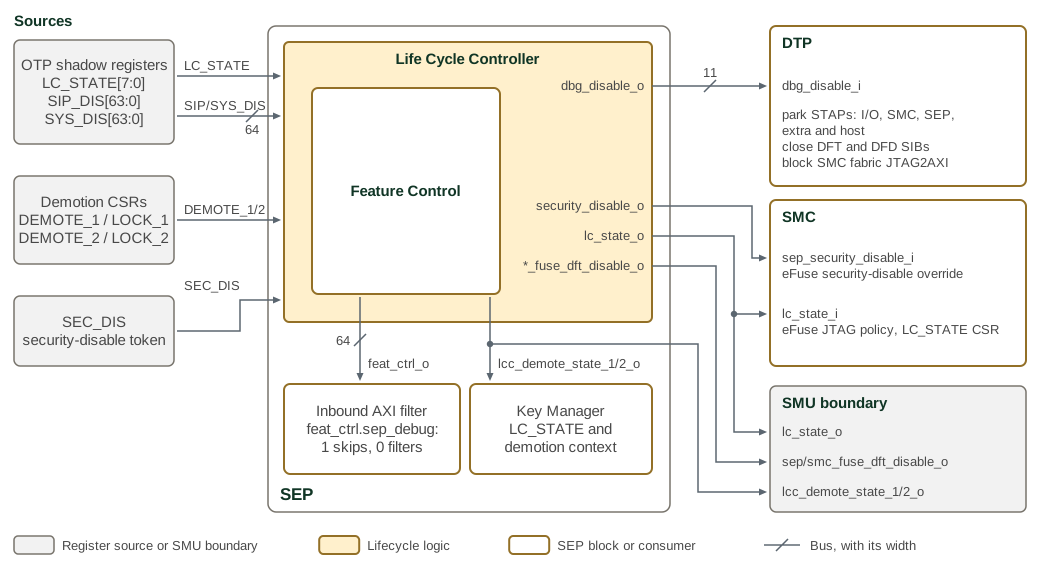
In Figure 6, the OTP shadow registers, the demotion CSRs and the security-disable token feed the Life Cycle Controller, and each named output runs to the block that consumes it; a slashed line carries its bus width. Table 3 gives the effect of each control on its consumer. The demotion CSRs clear on SEP cold reset, and security disable overrides the normal feature restrictions.
| Control | Consumer and effect |
|---|---|
|
DTP: disables selected STAPs, SIBs and SMC-fabric JTAG2AXI access |
|
SMC: eFuse JTAG access policy and the |
|
SMC |
|
SMU boundary outputs for adopter DFT insertion; each gates its DFT OTP access paths |
|
SEP inbound AXI filter: |
|
Key Manager: lifecycle and demotion context. The demotion state also reaches the SMU boundary. |
The subsystem chapters (SEP, SMC, DTP) follow immediately; see the Composition section above for roles and cross-references.